


26
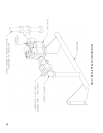
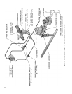
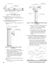
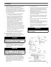
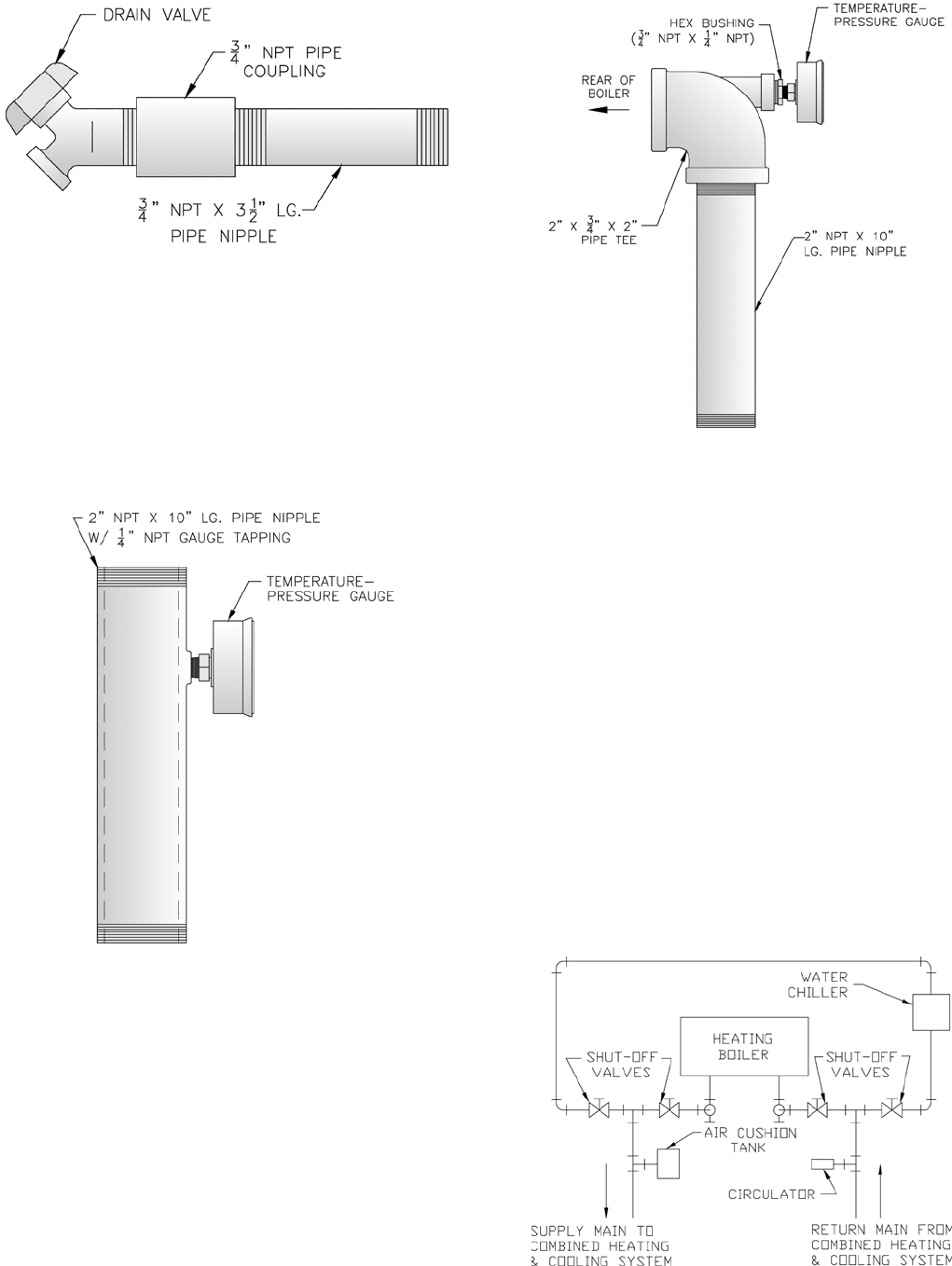
D. Install Drain Valve in rear of Left End Section,
Tapping “G”. See Figure 19. Components are located
in Water Trim Carton.
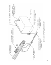
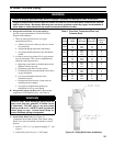
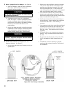
E. Install Temperature-Pressure Gauge. Components
are located in Water Trim Carton.
1. Standard Temperature - Pressure Gauge Piping. See
Figure 20.
Figure 19: Drain Piping Installation
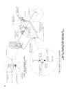
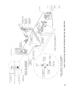
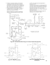
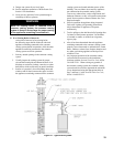
Figure 22: Recommended Piping for Combination
Heating & Cooling (Refrigeration) System
a. Install 2” NPT x 10” lg. nipple with gauge
tapping into Supply Tapping “A”. See Figure 3.
Gauge tapping should face forward.
b. Insert Temperature-Pressure Gauge. Tighten
by applying pressure to square shank on back
of gauge. DO NOT APPLY PRESSURE ON
GAUGE CASE since this may ruin gauge
calibration.
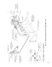
2. Alternate Temperature-Pressure Gauge Piping. See
Figure 21.
a. Install 2 NPT x 10” Nipple into Supply Tapping
“A”. See Figure 3.
Figure 20: Temperature-Pressure Gauge
Installation
Figure 21: Alternate Temperature-Pressure Gauge
Installation
b. Install 2 NPT x ¾ NPT x 2 NPT Tee (provided)
or 2 NPT x 2 NPT x ¾ NPT Tee (installer
furnished). ¾ NPT leg should face forward.
c. Install ¾ NPT x ¼ NPT Bushing.
d. Insert Temperature-Pressure Gauge. Tighten
by applying pressure to square shank on back
of gauge. DO NOT APPLY PRESSURE ON
GAUGE CASE since this may ruin gauge
calibration.
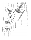
F. Connect system supply and return piping to boiler.
See Figure 23. Also consult I=B=R Installation and
Piping Guides. Maintain minimum ½ inch clearance
from hot water piping to combustible materials.
1. If boiler is used in connection with refrigeration
systems, boiler must be installed with chilled
medium piped in parallel with heating boiler using
appropriate valves to prevent chilled medium from
entering boiler. See Figure 22. Also consult I=B=R
Installation and Piping Guides.