


15
III. Gas Control System Assembly (Knockdown Boilers)
A. 24V Standing Pilot Control System
Install Gas Control System. All components are
located in Combination Boiler Parts and Control
Carton.
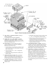
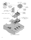
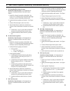
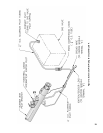
1. Install Gas Control Assembly on Manifold. See
Figure 10. Use thread (joint) compound (pipe dope)
resistant to action of liqueed petroleum gas.
2. Install pilot burner piping and controls. See Figure
10.
3. Connect Thermocouple Lead to Gas Valve.
4. Mount Transformer (continuous circulation) or
Control Center (intermittent circulation) to Junction
Box.
a. Canada only - loop 4” nylon cable tie between
junction box and transformer/control center.
b. Attach transformer/control center to junction
box.
B. EI (Intermittent Ignition)
Install Gas Control System. All components are
located in Combination Boiler Parts and Control
Carton.
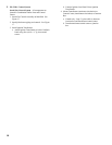
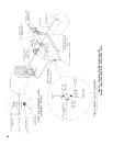
1. Install Gas Control Assembly on Manifold. See
Figure 11. Use thread (joint) compound (pipe dope)
resistant to action of liqueed petroleum gas.
2. Install pilot burner piping and controls.
a. Honeywell EI
i. USA - See Figure 12.
ii. Canada - See Figure 13.
3. Install Ignition Module.
a. Attach Ignition Control Mounting Bracket to
Jacket Vestibule Panel using two (2) #8 x ½”
sheet metal screws.
b. Attach Honeywell Ignition Module to Mounting
Bracket using two (2) #8 x ½” sheet metal
screws.
c. Connect pilot ground wire and ignitor/sensor
lead(s) to ignition module. Refer to “Section VII:
Electrical” for connection details.
4. Mount Transformer (continuous circulation) or
Control Center (intermittent circulation) to Junction
Box. See Figure 8.
a. Canada only - loop 4” nylon cable tie between
junction box and transformer/control center.
b. Attach transformer/control center to junction
box.
C. OP Control System
Install Gas Control System. All components are
located in Combination Boiler Parts and Control
Carton.
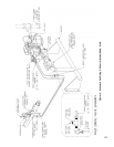
1. Install Gas Control Assembly on Manifold. See
Figure 14. Use thread (joint) compound (pipe dope)
resistant to action of liqueed petroleum gas.
2. Install pilot burner piping and controls. See Figure
14.
3. Connect Thermocouple Lead to Gas Valve.
4. Mount Transformer (continuous circulation) or
Control Center (intermittent circulation) to Junction
Box.
a. Canada only - loop 4” nylon cable tie between
junction box and transformer/control center.
b. Attach transformer/control center to junction
box.
D. OP-CSD-1 Control System
Install Gas Control System. All components are
located in Combination Boiler Parts and Control
Carton.
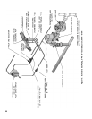
1. Install Gas Control Assembly on Manifold. See
Figure 15. Use thread (joint) compound (pipe dope)
resistant to action of liqueed petroleum gas.
2. Mount pilot switch.
3. Install pilot burner piping and controls. See Figure
15.
4. Connect Thermocouple lead to pilot switch.
5. Mount Transformer (continuous circulation) or
Control Center (intermittent circulation) to Junction
Box.
6. Attach transformer/control center to junction box.
E. EP Control System
Install Gas Control System. All components are
located in Combination Boiler Parts and Control
Carton.
1. Install Gas Control Assembly on Manifold. See
Figure 16.
2. Install pilot burner piping and controls. See Figure
16.
3. Install Ignition Transformer.
a. Attach Ignition Transformer to Jacket Vestibule
Panel using four (4) #8 x ½” lg. sheet metal
screws.
b. Connect Ignition Lead from Pilot to Ignition
Transformer.
4. Mount Transformer (continuous circulation) or
Control Center (intermittent circulation) to Junction
Box.
a. Canada only - loop 4” nylon cable tie between
junction box and transformer/control center.
b. Attach transformer/control center to junction
box.