


35
E. Alliance SL™ Water Heater (if used). May be used
with Intermittent Circulation only.
Refer to Alliance SL™ Installation, Operating
and Service Instructions for wiring, piping and
additional information.
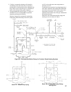
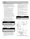
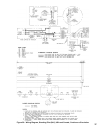
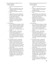
F. Vent Damper Sequence of Operation. See Figure 28
for schematic wiring diagram.
1. The Vent Damper is continuously powered at
Terminal 1.
2. When there is a call for heat, the damper relay coil
is energized through Terminal 5 if all limits ahead of
the damper are satised.
3. The relay coil closes contacts which energize the
damper motor, causing the damper to open.
4. When the damper blade reaches the fully open
position, power is sent back to the ignition circuit
through Terminal 2 and the damper motor is de-
energized.
5. When the call for heat is satised, the damper
relay coil is de-energized - closing contacts which
energize the damper motor. This causes the damper
to close. When the damper blade reaches the fully
closed position, the damper motor is de-energized.
POWER FAILURE - The damper blade will stop in the
position it was in when power failed. (Combustion
can never take place unless the damper blade is in
the fully open position).
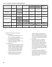
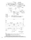
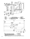
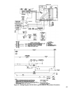
G. Sequence of Operation and Wiring. Refer to Table
10 for the appropriate control system.
H. Optional Low-Water Cut-Off Wiring. See Figures 45
through 48.
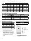
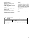
Table 9: Heat Anticipator Settings
Control System
Heat Anticipator Setting *
Continuous Circulation Intermittent Circulation
24V Standing Pilot 1.1 0.3
24V Electronic Ignition
USA: 0.9
0.3
Canada: 1.2
* If room is heated above thermostat temperature setting, reduce heat anticipator setting by 0.1 or
0.2 amps. If boiler short cycles without room reaching desired temperature, increase heat anticipator
by 0.1 or 0.2 amps.