


52
WARNING
Completely read, understand and follow all
instructions in this manual before attempting
start-up.
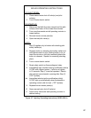
A. Safe operation and other performance criteria were met
with the gas manifold and control assembly provided
on boiler when boiler underwent tests specied in
American National Standard for Gas-Fired Low-
Pressure Steam and Hot Water Boilers, ANSI Z21.13.
B. Check Main Burners. Main burners must be properly
located on support bracket in Base Rear Panel, seated
on Main Burner Orices, and secured with hitch pin
clips.
C. Verify that the venting, water piping, gas piping
and electrical system are installed properly. Refer to
installation instructions contained in this manual.
D. Conrm all electrical, water and gas supplies
are turned off at the source and that vent is clear of
obstructions.
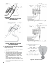
E. FILL ENTIRE HEATING SYSTEM WITH WATER
and vent air from system. Use following procedure on
a Series Loop or multi-zoned system installed as per
Figure 23 to remove air from system when lling.
WARNING
The maximum operating pressure of this boiler is
50 psig. Never exceed this pressure. Do not plug
or modify pressure relief valve.
1. Close full port ball valve in boiler supply piping.
2. Isolate all zones by closing zone valves or shut-off
valves in supply and return of each zone(s).
3. Attach a hose to the vertical purge valve located
prior to the full port ball valve in the system supply
piping. (Note - Terminate hose in ve gallon bucket
at a suitable oor drain or outdoor area).
4. Starting with one circuit at a time, open zone valve
or shut-off valve in system supply and return piping.
5. Open purge valve.
6. Open ll valve (Make-up water line should be
located directly after full port ball valve in system
supply piping between air scoop and expansion
tank).
7. Allow water to overow from bucket until discharge
from hose is bubble free for 30 seconds.
8. Close the open zone valve or shut-off valve for the
zone being purged of air, then open the zone valve
or shut-off valve for the next zone to be purged.
Repeat this step until all zones have been purged. At
completion, open all zone valves or shut-off valves.
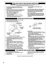
VIII. System Start-Up
9. Close purge valve, continue lling the system
until the pressure gauge reads the desired cold ll
pressure. Close ll valve.
(Note - If make-up water line is equipped with
pressure reducing valve, adjust pressure reducing
valve to desired cold ll pressure. Follow ll valve
manufacturer’s instructions).
10. Open isolation valve in boiler supply piping.
11. Remove hose from purge valve.
F. Conrm that the boiler and system have no water
leaks.
G. Prepare to check operation.
1. Obtain gas heating value (in Btu per cubic foot)
from gas supplier.
2. Connect manometer to pressure tap on gas valve.
Use 1/8 NPT tapping provided.
3. Temporarily turn off all other gas-red appliances.
4. Turn on gas supply to the boiler gas piping.
5. Conrm that the supply pressure to the gas valve is
14 in. w.c. or less.
6. Open the eld installed manual gas shut-off valve
located upstream of the gas valve on the boiler.
7. Using soap solution, or similar non-combustible
solution, electronic leak detector or other approved
method. Check that boiler gas piping, valves, and
all other components are leak free. Eliminate any
leaks.
8. Purge gas line of air.
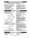
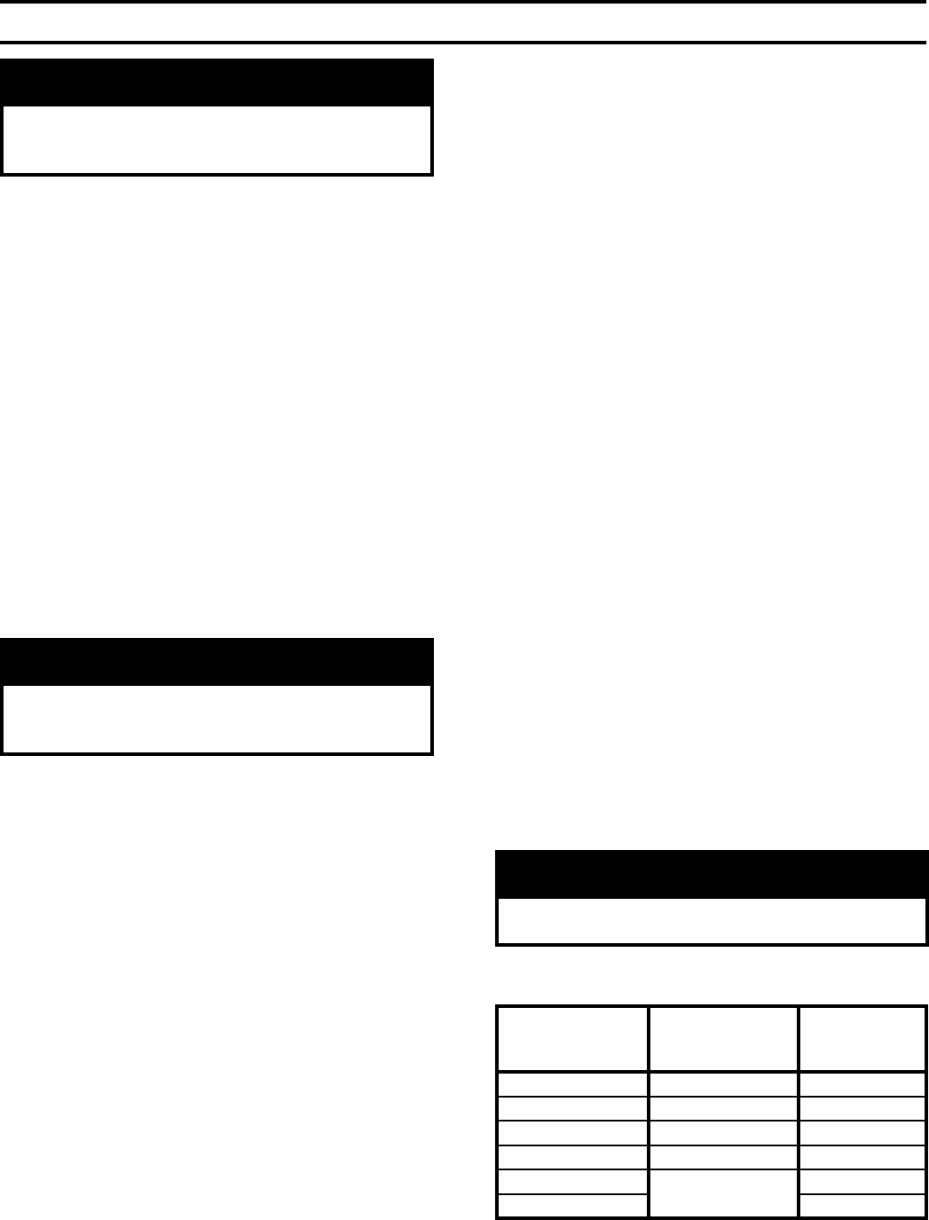
H. Follow Lighting or Operating Instructions to place
boiler in operation. Refer to label on inside of Front
Removable Panel or appropriate Figure as listed in
Table 11.
DANGER
Do not use matches, candles, open ames or
other ignition source to check for leaks.
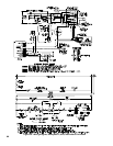
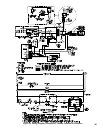
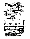
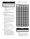
Ignition System
Lighting or
Operating
Instructions
Pilot Flame
Illustration
Standing Pilot (24) Figure 43 Figure 48
Honeywell EI Figure 44 Figure 49
OP Figure 45 Figure 50
EP Figure 46 Figure 51
OP-CSD-1
Figure 47
Figure 50
EP-CSD-1 Figure 51
Table 11: Lighting and Operating Instructions