


34
VII. Electrical
WARNING
Failure to properly wire electrical connections to the boiler may result in serious physical harm.
Electrical power may be from more than one source. Make sure all power is off before attempting any
electrical work.
Each boiler must be protected with a properly sized fused disconnect.
Never jump out or make inoperative any safety or operating controls.
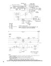
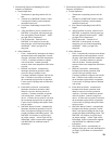
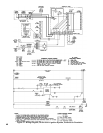
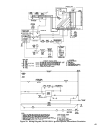
The wiring diagrams contained in this manual are for reference purposes only. Each boiler is shipped with
a wiring diagram attached to the front door. Refer to this diagram and the wiring diagram of any controls
used with the boiler. Read, understand and follow all wiring instructions supplied with the controls.
DANGER
Positively assure all electrical connections are unpowered before attempting installation or service of
electrical components or connections of the boiler or building. Lock out all electrical boxes with padlock
once power is turned off.
A. Install Boiler Wiring
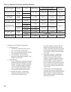
1. Knockdown boilers only. Locate wiring harnesses
in Combination Boiler Parts and Control Carton.
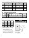
Refer to Table 10 and connect wiring as shown on
the appropriate wiring diagram.
2. Connect supply wiring and electrically ground boiler
in accordance with requirements of authority having
jurisdiction, or in absence of such requirements the
National Electrical Code, ANSI/NFPA 70 and/or
CSA C22.1 Electrical Code.
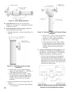
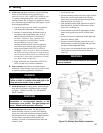
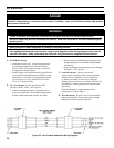
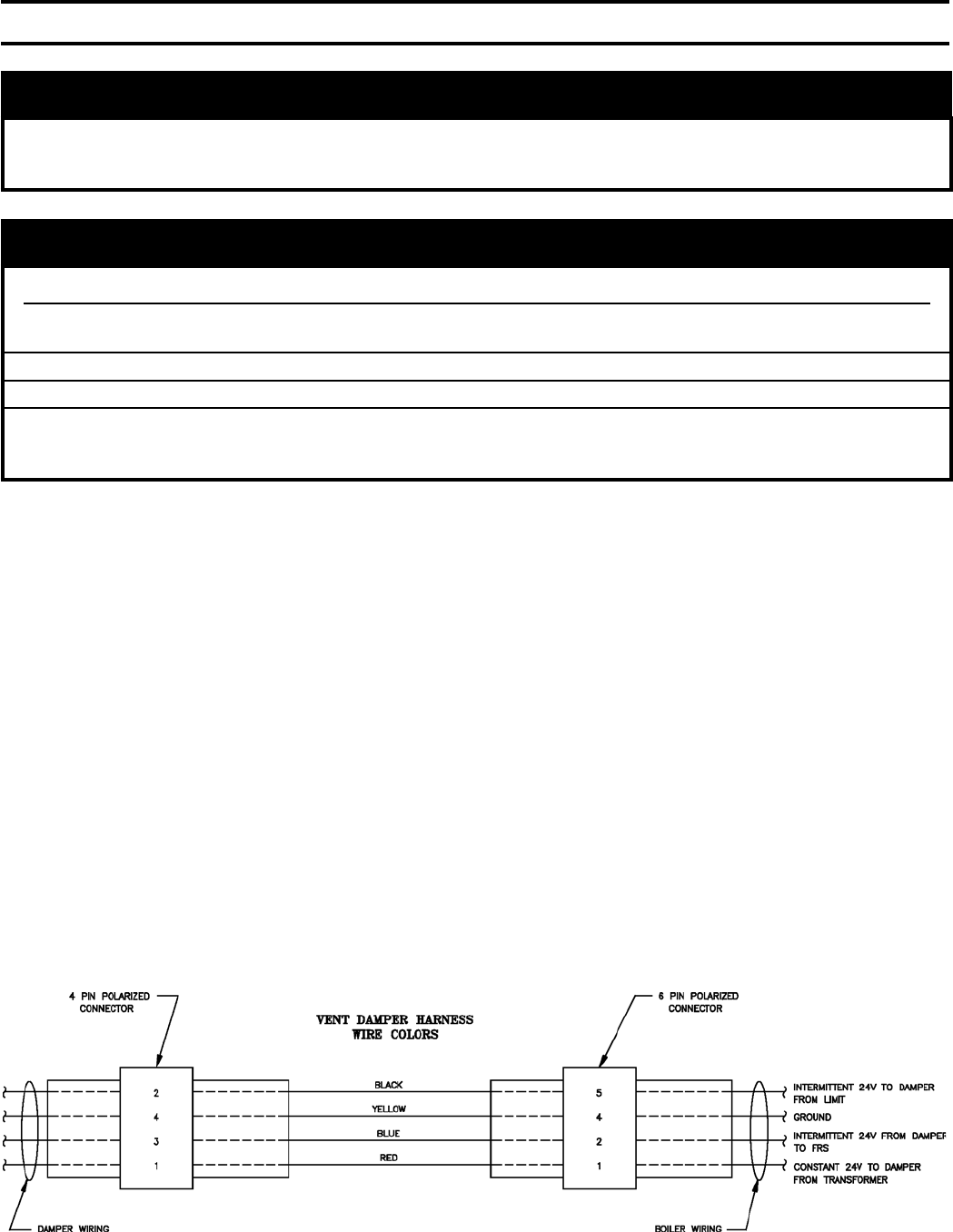
B. Wire Vent Damper (if used; required on 805H,
optional on 806H - 810H). See Figure 26.
1. Attach Vent Damper Harness to mounting hole in
Jacket Left Side Panel. Install Cable Clamp around
exible conduit and attach to Jacket Top Panel.
2. Remove factory installed Jumper Plug from Vent
Damper Receptacle on Vestibule Wiring Harness
and discard.
3. Plug Vent Damper Harness Plug into Vent Damper
Receptacle. See Figure 26.
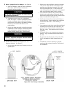
C. Install thermostat. Locate on inside wall
approximately 4 feet above oor. Do not install on
outside wall, near replace, or where inuenced
by drafts or restricted air ow, hot or cold pipes,
lighting xtures, television, or sunlight. Allow free air
movement by avoiding placement of furniture near
thermostat.
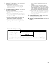
Set heat anticipator to match control system
requirements. Refer to Table 9.
D. Wire thermostat. Provide Class II circuit between
thermostat and boiler. Refer to appropriate wiring
diagram for control system being used.
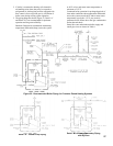
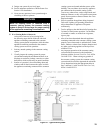
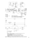
Figure 28: Vent Damper Schematic Wiring Diagram