


25
IV. Water Trim and Piping
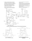
A. Design and install boiler and system piping to
prevent oxygen contamination of boiler water and
frequent water additions.
1. There are many possible causes of oxygen
contamination such as:
a. Addition of excessive make-up water as a result
of system leaks.
b. Absorption through open tanks and ttings.
c. Oxygen permeable materials in the distribution
system.
2. In order to insure long product life, oxygen sources
must be eliminated. This can be accomplished by
taking the following measures:
a. Repairing system leaks to eliminate the need for
addition of make-up water.
b. Eliminating open tanks from the system.
c. Eliminating and/or repairing ttings which allow
oxygen absorption.
d. Use of non-permeable materials in the
distribution system.
e. Isolating the boiler from the system water by
installing a heat exchanger.
f. Use properly designed and operating air
elimination devices in water piping.
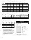
B. Design boiler piping and ow rate to obtain proper
temperature rise though the boiler. (See Table 4)
WARNING
Pressure relief valve discharge piping must be
piped such that the potential of severe burns
is eliminated. DO NOT pipe in any area where
freezing could occur. DO NOT install any shut off
valves, plugs or caps. Consult Local Codes for
proper discharge piping arrangement.
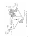
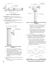
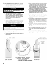
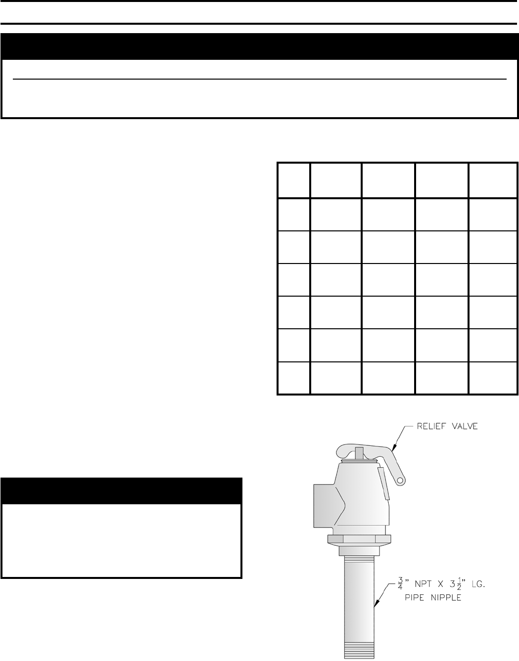
C. Install Safety Relief Valve. See Figure 18.
Components are located in Water Trim Carton. Safety
Relief Valve must be installed with spindle in vertical
position.
1. Install ¾” NPT x 3½” lg. nipple in tapping “C”. See
Figure 3.
2. Install safety relief valve on ¾” NPT nipple.
WARNING
Failure to properly pipe boiler may result in improper operation and damage to boiler or structure.
Oxygen contamination of boiler water will cause corrosion of iron and steel boiler components, and can
lead to boiler failure. Burnham’s Warranty does not cover problems caused by oxygen contamination of
boiler water or scale (lime) build-up caused by frequent addition of water.
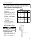
Table 4: Flow Rate, Temperature Rise, and
Pressure Drop
Boiler
Model
Flow Rate
(GPM)
Temp. Rise
Thru Boiler
Min. Boiler
Piping NPT
Boiler
Pressure
Drop
805H
21
14
10
20° F
30° F
40° F
1½”
1¼”
1¼”
3’
2’
1’
806H
26
17
13
20° F
30° F
40° F
1½”
1½”
1¼”
3’
2’
1’
807H
31
20
15
20° F
30° F
40° F
2”
1½”
1¼”
3’
2’
1’
808H
36
24
18
20° F
30° F
40° F
2”
1½”
1½”
3’
2’
1’
809H
40
27
20
20° F
30° F
40° F
2”
2”
1½”
3’
2’
1’
810H
45
30
22
20° F
30° F
40° F
2”
2”
1½”
3’
2’
1’
Figure 18: Safety Relief Valve Installation