


39
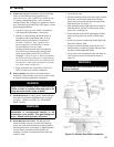
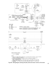
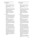
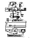
2. Electronically Supervised Standing Pilot (OP)
Sequence of Operation
a. Normal Operation
i. Thermostat or operating control calls for
heat.
ii. Terminal #6 of RM7890C Burner Control
is energized, initiating a microcomputer
monitored circuit test.
iii. Pilot Flame Establishing Period (PFEP)
begins.
iv. After pilot ame is proven, terminal #9 of
RM7890C is energized, allowing main gas
ow and ignition of main burners. “Main”
gas light will be illuminated.
v. Call for heat ends. Terminal #6 of
RM7890C is de-energized, in turn de-
energizing gas valves and extinguishing
main ame. “Main” gas light is de-
energized.
b. Safety Shutdown
i. Limit: Automatically interrupts main burner
operation when water temperature exceeds
set point. Maximum allowable temperature
is 250°F. Circulator continues to operate
with call for heat. Normal operation
resumes when water temperature falls below
set point.
ii. Blocked Vent Switch: Automatically
interrupts main burner operation when
excessive ue gas spillage occurs.
Circulator continues to operate with call for
heat. If blocked vent switch is activated
do not attempt to place boiler in operation.
Correct cause of spillage and reset blocked
vent switch.
iii. Flame Roll-out Switch: Automatically
interrupts main burner operation when
ames or excessive heat are present in
vestibule. Circulator continues to operate
with call for heat. Control is single use
device. If ame roll-out switch is activated,
do not attempt to place boiler in operation.
Correct cause of spillage and replace ame
roll-out switch.
iv. RM7890C Burner Control: Automatically
interrupts main burner operation if a pilot
ame is not detected during the four or ten
second pilot ame establishing period. The
RM7890C will lockout or recycle based
on jumper settings. “Alarm” light will be
illuminated. Refer to instructions supplied
with RM7890C for additional control
information.
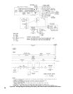
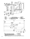
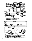
3. Electronically Supervised Standing Pilot (OP-CSD-1)
Sequence of Operation
a. Normal Operation
i. Thermostat or operating control calls for
heat.
ii. Terminal #6 of RM7890C Burner Control
is energized, initiating a microcomputer
monitored circuit test.
iii. Pilot Flame Establishing Period (PFEP)
begins.
iv. After pilot ame is proven, terminal #9 of
RM7890C is energized, allowing main gas
ow and ignition of main burners. “Main”
gas light will be illuminated.
v. Call for heat ends. Terminal #6 of
RM7890C is de-energized, in turn de-
energizing gas valves and extinguishing
main ame. “Main” gas light is de-
energized.
b. Safety Shutdown
i. Limit: Automatically interrupts main burner
operation when water temperature exceeds
set point. Maximum allowable temperature
is 250°F. Circulator continues to operate
with call for heat. Normal operation
resumes when water temperature falls below
set point.
ii. Blocked Vent Switch: Automatically
interrupts main burner operation when
excessive ue gas spillage occurs.
Circulator continues to operate with call for
heat. If blocked vent switch is activated
do not attempt to place boiler in operation.
Correct cause of spillage and reset blocked
vent switch.
iii. Flame Roll-out Switch: Automatically
interrupts main burner operation when
ames or excessive heat are present in
vestibule. Circulator continues to operate
with call for heat. Control is single use
device. If ame roll-out switch is activated,
do not attempt to place boiler in operation.
Correct cause of spillage and replace ame
roll-out switch.
iv. RM7890C Burner Control: Automatically
interrupts main burner operation if a pilot
ame is not detected during the four or ten
second pilot ame establishing period. The
RM7890C will lockout or recycle based
on jumper settings. “Alarm” light will be
illuminated. Refer to instructions supplied
with RM7890C for additional control
information.
v. Pilot Safety Switch: Automatically de-
energizes main gas valve and interrupts pilot
gas supply if pilot ame is not detected at
any time.