


6
I. Pre-Installation
WARNING
Carefully read all instructions before installing
boiler. Failure to follow all instructions in proper
order can cause personal injury or death.
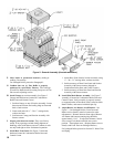
A. Inspect shipment carefully for any signs of damage.
All equipment is carefully manufactured, inspected
and packed. Our responsibility ceases upon delivery
of boiler to carrier in good condition. Any claim
for damage or shortage in shipment must be led
immediately against carrier by consignee. No claims
for variances or shortages will be allowed by Boiler
Manufacturer, unless presented within sixty (60) days
after receipt of equipment.
B. Installation must conform to the requirements of
the authority having jurisdiction. In the absence of
such requirements, installation must conform to the
National Fuel Gas Code, NFPA 54/ANSI Z223.1 and/or
CAN/CSA B149.1 Installation Codes. Where required
by the authority having jurisdiction, the installation
must conform to the Standard for Controls and Safety
Devices for Automatically Fired Boilers, ANSI/ASME
No CSD-1.
C. Provide clearance between combustible material and
boiler jacket (following clearances are minimums):
1. USA, 805H-807H: listed for Alcove installation
a. Front: 18”
b. Top: 36”
c. Draft hood, rear, sides and ue connector: 6”
WARNING
Appliance is design certied for installation on
noncombustible ooring only. For installation
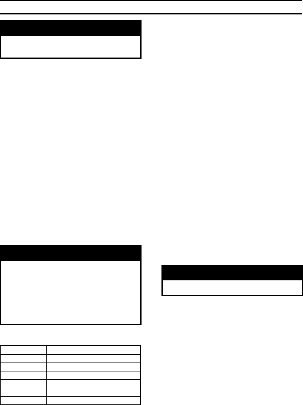
on combustible ooring only when installed on
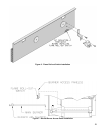
special base listed in Table 2. Boiler must not be
installed on carpeting. When boiler is installed on
concrete which is over a material that is subject
to melting (PVC, PEX radiant tubing, etc.), the
special base must be used. A concrete pad is not
sufcient to protect combustible ooring.
2. USA, 808H-810H: for installation in room which is
large in comparison with size of boiler.
a. Front: 18”
b. Top: 51½”
c. Draft hood, rear, sides, and ue connector: 6”
3. Canada, 805H-810H:
a. Top and front: 18” (45.7 cm)
b. Flue, rear and sides: 6” (15.2 cm)
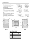
D. Provide clearance for servicing and proper operation
(following clearances are recommended and may be
reduced to minimum clearances shown above):
1. Single boiler, 805H-807H, Front/Top: 24” (61.0 cm)
2. Single boiler, 808H-810H, Front/Top: 48”
(122.0 cm)
3. Multiple/modular boiler, USA /Canada, Sides: 1”
(2.5 cm)
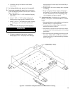
E. Install boiler on level oor as close to chimney as
possible. For basement installation provide a solid base
such as concrete or masonry construction if oor is not
level or if water may be encountered on oor around
boiler.
F. Protect gas ignition system components from
water (dripping, spraying, rain, etc.) during boiler
operation and service (circulator replacement, control
replacement, etc.).
G. Provide combustion and ventilation air in accordance
with applicable provisions of local building codes,
or the National Fuel Gas Code, NFPA 54/ANSI
Z223.1, Air for Combustion and Ventilation; or CAN/
CSA B149.1, Venting Systems and Air Supply for
Appliances.
WARNING
Adequate combustion and ventilation air must be
provided to assure proper combustion.
The following guideline is based on the
National Fuel
Gas Code, NFPA 54/ANSI Z223.1.
1. Determine volume of space (boiler room). Rooms
communicating directly with space (through
permanent openings not furnished with doors) are
considered part of space.
Volume [ft3] = Length [ft] x Width [ft] x Height [ft]
2. Determine Total Input of all appliances in space.
Round result to nearest 1,000 Btu per hour (Btuh).
3. Determine type of space. Divide Volume by Total
Input.
a. If result is greater than or equal to 50 ft3 per
1,000 BtuH, space is considered an unconned
space.
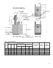
Boiler Model Special Base Part Number
805H 61816055
806H 61816065
807H 61816075
808H 61816085
809H 61816095
810H 61816105
Table 2: Special Base Required for Installation on
Combustible Flooring