


12
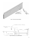
M. Attach Flame Roll-out Switch to Burner Access Panel.
See Figure 6. Flame Roll-out Switch and hardware
are located in Combination Boiler Parts and Control
Carton. Flame Roll-out Switch is a single use device
- do not test with heat - switch cannot be reset.
1. Cut insulation from semicircular notch at right
end of the burner access panel. Models 808H
- 810H have two (2) burner access panels. Remove
insulation from notch of right side burner access
panel only.
2. Attach Flame Roll-out Switch Mounting Bracket to
burner access panel with (1) #8 x ½” lg. sheet metal
screw.
3. Attach Flame Roll-out Switch to mounting bracket
with (1) #8 x ¾” lg. sheet metal screw.
N. Install Burner Access Panel(s). Locate Burner Access
Panel(s) in Combination Boiler Parts and Control
Carton. Engage Burner Access Panel holes with
projections on Base Front Panel. See Figure 5.
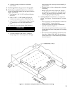
O. Install Immersion Well(s).
1. Remove Immersion Well(s) from Combination
Boiler Parts and Control Carton..
2. Insert Immersion Well in Tapping D. See Figure 3.
3. If second limit or operating control is used, insert
immersion well in Tapping E. If vertical gas
piping is to be installed inside of boiler jacket, it
is recommended that second limit be installed in
system piping.
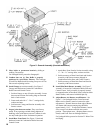
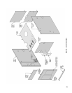
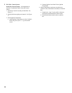
P. Install Jacket. See Figure 8.
1. Locate four (4) Jacket Attachment Brackets in
Combination Boiler Parts and Control Carton.
Attach to Front Base Panel and Rear Base Panels
with #8 sheet metal screws. See Figure 5.
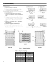
2. Hang Left Side Panel and Right Side Panel onto
Jacket Attachment Brackets.
3. Attach Lower Rear Panel to Left and Right Side
Panels. Do not tighten sheet metal screws.
4. Attach Upper Rear Panel to Lower Rear Panel. Do
not install three (3) upper screws.
5. Remove Rating Label from envelope marked
“RATING LABEL ENCLOSED”. Remove
Combustible Clearance Label from Combination
Boiler Parts and Controls Carton. Attach to
Vestibule Panel in locations shown.
6. Attach Vestibule Panel to Left Side and Right Side
Panels.
7. Attach Lower Front Tie Bar to Left Side and Right
Side Panels.
8. Engage Upper Front Panel in slots on Left Side
and Right Side Panels. Place Top Panel in position.
Attach Top Panel to Left Side, Right Side and Upper
Rear Panels.
9. Tighten all jacket screws.
10. Afx Lighting/Operating Instructions Label and
Wiring Diagram Label to inside of Front
Removable Door. Labels are located in
Combination Boiler Parts and Control Carton.
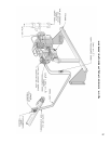
Q. Install Junction Box. See Figure 8. Attach junction
box to inside of Left Side Panel with ¼” - 20 x ¼” lg.
machine screw (located in Combination Boiler Parts
and Control Carton).
R. Install Limit Control. Locate limit in Combination
Boiler Parts and Control Carton. Insert limit probe
into left immersion well as far as possible. Tighten set
screw.
S. Install Auxiliary Limit or operating control (if used).
Insert control probe into right immersion well as far as
possible. Tighten set screw.
T. Install Gas Control Assembly. Refer to Section III,
Gas Control System Assembly (Knockdown Boilers).
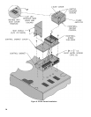
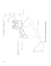
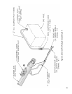
U. EP and OP System: See Figure 9.
1. Install pre-wired EP/OP Control Cabinet Assembly
to right front corner of jacket top panel.
2. Install Honeywell RM7890 Control (located in
RM7890 Control Carton).
3. Remove RM7890’s Dust Cover. With a pair of side
cutters, carefully snip both wire leads to the brown
resistor labelled “JR2” and discard it. Replace Dust
Cover.
4. Install Honeywell R7847 Flame Amplier.
5. Install heat shield.