


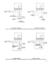
59
CAUTION
Avoid operating this boiler in an environment
where saw dust, loose insulation bers, dry wall
dust, etc. are present. If boiler is operated under
these conditions, the burner interior and ports
must be cleaned and inspected daily to insure
proper operation.
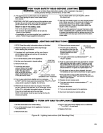
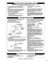
a. Loosen lock screw.
b. Close air adjustment until yellow tips appear on
ames.
c. Slowly open air adjustment until clearly dened
inner cones are visible.
d. Tighten lock screw.
4. Adjust thermostat to normal setting.
J. Check thermostat or operating control operation.
Raise and lower temperature setting to start and stop
boiler operation.
K. Check ignition system shut-off.
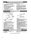
1. Standing Pilot (24V): Disconnect thermocouple
lead at Gas Valve. Gas Valve must close and pilot
and main burners extinguish. If not, replace the gas
valve.
2. Honeywell EI: Disconnect ignitor/sensor cable from
ignition module. Gas valve must close and pilot and
main burners extinguish. If not, measure voltage
across gas valve terminals “TH” and “TR”.
a. If voltage is not present, replace gas valve.
b. If voltage is present, replace ignition module.
3. EP and OP: Refer to instructions supplied with the
Honeywell RM7890 Burner Control.
L. Check Limit(s).
1. Adjust thermostat to highest setting.
2. Observe temperature gauge. When temperature
exceeds limit set point main burners should
extinguish.
3. Adjust limit to setting above observed reading. Main
burners should reignite.
4. Adjust thermostat to lowest setting. Adjust limit to
desired setting.
M. Adjust gas input rate to boiler. Natural Gas.
1. Adjust thermostat to highest setting.
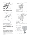
2. Check manifold gas pressure. Manifold pressure
is listed on rating label. Adjust gas valve pressure
regulator as necessary (turn adjustment screw
counterclockwise to decrease manifold pressure, or
clockwise to increase manifold pressure). If pressure
can not be attained, check gas valve inlet pressure.
If less than minimum gas supply pressure listed on
rating label, contact gas supplier for assistance.
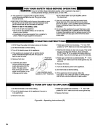
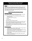
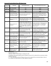
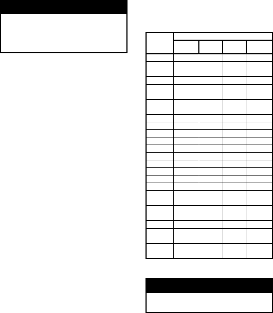
3. Clock gas meter for at least 30 seconds. Use Table
12 to determine gas ow rate in Cubic Feet per
Hour.
Seconds
for One
Revolution
Size of Gas Meter Dial
One-Half
Cu. Ft.
One
Cu. Ft.
Two
Cu. Ft.
Five
Cu. Ft.
30 60 120 240 600
32 56 113 225 563
34 53 106 212 529
36 50 100 200 500
40 45 90 180 450
38 47 95 189 474
40 45 90 180 450
42 43 86 172 430
44 41 82 164 410
46 39 78 157 391
48 37 75 150 375
50 36 72 144 360
52 35 69 138 346
54 33 67 133 333
56 32 64 129 321
58 31 62 124 310
60 30 60 120 300
62 29 58 116 290
64 29 56 112 281
66 29 54 109 273
68 28 53 106 265
70 26 51 103 257
72 25 50 100 250
74 24 48 97 243
76 24 47 95 237
78 23 46 92 231
80 22 45 90 225
Table 12: Input Rate
4. Determine Input Rate. Multiply gas ow rate by gas
heating value.
Warning
Failure to properly adjust gas input rate will result
in over ring or under ring of the appliance.
Improper and unsafe boiler operation may result.
5. Compare measured input rate to input rate stated on
rating label.
a. Boiler must not be overred. Reduce input rate
by decreasing manifold pressure. Do not reduce
more than 0.3 inch w.c. If boiler is still overred,
contact your Burnham distributor or Regional
Ofce for replacement Gas Orices.