


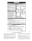
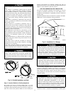
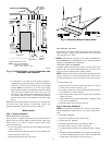
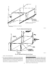
c. If combustion air is taken from the outdoors through a
single opening or duct (horizontal or vertical) commencing
within 12 in. of the top of the confined space, the opening
and duct must have at least 1 sq in. of free area per 3000
Btuh of the total input for all equipment within the confined
space and not less than the sum of the areas of all vent
connectors in the confined space. Equipment clearances to
the structure shall be at least 1 in. from the sides and back
and 6 in. from the front of the appliances. See Table 2 and
Fig. 8.
When ducts are used, they must be of the same cross sectional area
as the free area of the openings to which they connect. The
minimum dimension of ducts must not be less than 3 in.
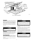
INSTALLATION
Step 1—Upflow Installation
BOTTOM RETURN AIR INLET
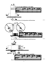
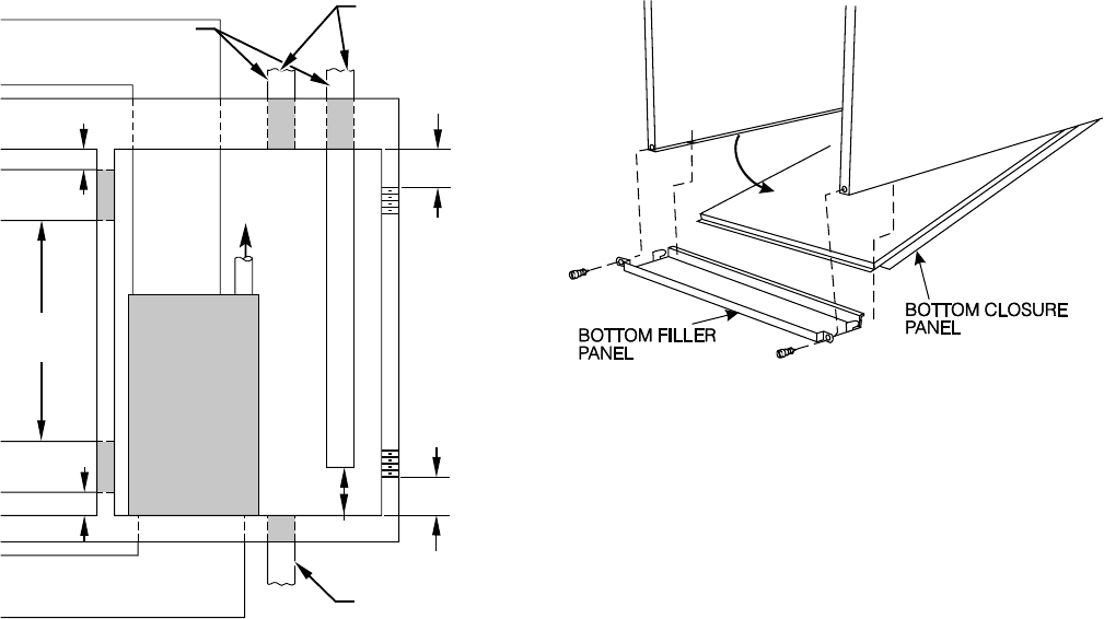
These furnaces are shipped with bottom closure panel installed in
bottom return-air opening. Remove and discard this panel when
bottom return air is used. To remove bottom closure panel,
perform the following:
1. Tilt or raise furnace and remove 2 screws holding bottom filler
panel. (See Fig. 9.)
2. Rotate bottom filler panel downward to release holding tabs.
3. Remove bottom closure panel.
4. Reinstall bottom filler panel and screws.
SIDE RETURN AIR INLET
These furnaces are shipped with bottom closure panel installed in
bottom return-air opening. This panel MUST be in place when
only side return air is used.
NOTE: Side return-air openings can be used in UPFLOW and
most HORIZONTAL configurations. Do not use side return-air
openings in DOWNFLOW configuration.
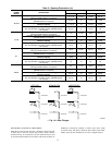
LEVELING LEGS (IF DESIRED)
In upflow position with side return inlet(s), leveling legs may be
used. (See Fig. 10.) Install field-supplied, 5/16 X 1 1/2 in. (max)
corrosion-resistant machine bolts, washers and nuts.
NOTE: Bottom closure must be used when leveling legs are used.
It may be necessary to remove and reinstall bottom closure panel
to install leveling legs. To remove bottom closure panel, see Fig.
9.
To install leveling legs:
1. Position furnace on its back. Locate and drill a hole in each
bottom corner of furnace. (See Fig. 10.)
2. For each leg, install nut on bolt and then install bolt and nut in
hole. (Install flat washer if desired.)
3. Install another nut on other side of furnace base. (Install flat
washer if desired.)
4. Adjust outside nut to provide desired height, and tighten inside
nut to secure arrangement.
5. Reinstall bottom closure panel if removed.
Step 2—Downflow Installation
NOTE: For downflow applications, this furnace is approved for
use on combustible flooring when any one of the 3 accessories are
used:
• Special Base, KGASB
• Cased Coil Assembly Part No. CD5 or CK5
• Coil Box Part No. KCAKC
1. Determine application being installed from Table 3.
2. Construct hole in floor per Table 3 and Fig. 11.
3. Construct plenum to dimensions specified in Table 3 and Fig.
11.
4. If downflow subbase, KGASB is used, install as shown in Fig.
12. If Coil Assembly Part No. CD5 or CK5 or Coil Box Part
No. KCAKC is used, install as shown in Fig. 13.
Fig. 8—Confined Space: Air for Combustion and
Ventilation from Outdoors
A02165
1 SQ IN.
PER
4000
BTUH*
DUCTS
TO
OUTDOORS
1 SQ IN.
PER 4000
BTUH
*
AIR
DUCTS
VENT
THROUGH
ROOF
D
B
A
C
E
1 SQ IN.
PER 4000
BTUH
*
DUCT
TO
OUTDOORS
AIR DUCTS
1 SQ IN.
PER 2000
BTUH
*
1 SQ IN.
PER 2000
BTUH
*
DUCTS
TO
OUTDOORS
12″ MAX
12
″ MAX
12″ MAX
Use any of the following
combinations of openings:
A & B C & D D & E F & G
NOTE:
*Minimum dimensions of 3 in.
CONFINED
SPACE
12″
MAX
12″
MAX
OUTDOORS
1 SQ IN.
PER
4000
BTUH*
F
G
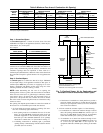
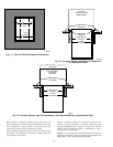
Fig. 9—Removing Bottom Closure Panel
A02098
8
→