


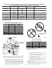
4. Verify natural gas input rate by clocking meter.
NOTE: Gas valve regulator adjustment cap must be in place for
proper input to be clocked.
a. Turn off all other gas appliances and pilots.
b. Run furnace for 3 minutes in heating operation.
c. Measure time (in sec) for gas meter to complete 1 revolu-
tion and note reading. The 2 cubic feet dial provides a more
accurate measurement of gas flow.
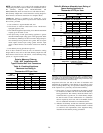
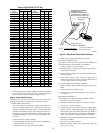
d. Refer to Table 8 for cubic ft of gas per hr.
e. Multiply gas rate (cu ft/hr) by heating value (Btu/cu ft) to
obtain input.
If clocked rate does not match required input from Step 1, increase
manifold pressure to increase input or decrease manifold pressure
to decrease input. Repeat steps b through e until correct input is
achieved. Re-install regulator seal cap on gas valve.
5. Set temperature rise.
The furnace must operate within the temperature rise ranges
specified on the furnace rating plate. Do not exceed tempera-
ture rise range specified on unit rating plate. Determine the
temperature rise as follows:
a. Place thermometers in return and supply ducts as close to
furnace as possible. Be sure thermometers do not see
radiant heat from heat exchangers. Radiant heat affects
temperature rise readings. This practice is particularly
important with straight-run ducts.
b. When thermometer readings stabilize, subtract return-air
temperature from supply-air temperature to determine air
temperature rise.
NOTE: Blower access door must be installed for proper tempera-
ture rise measurement.
NOTE: If the temperature rise is outside this range, first check:
1.) Gas input for heating operation.
2.) Derate for altitude if applicable.
3.) Return and supply ducts for excessive restrictions causing static
pressures greater than 0.50-in. wc.
4.) Dirty filter.
Disconnect 115-v electrical power before changing speed tap.
Failure to follow this warning could result in personal injury.
c. Adjust air temperature rise by adjusting blower speed.
Increase blower speed to reduce temperature rise. Decrease
blower speed to increase temperature rise.
d. Turn thermostat down below room temperature and re-
move blower access door.
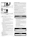
e. To change motor speed selection for heating, remove
blower motor lead from control HEAT terminal (See Fig.
39.) Select desired blower motor speed lead from one of the
other terminals and relocate it to the HEAT terminal (See
Table 7 for lead color identification). Reconnect original
lead to SPARE terminal.
f. Repeat steps a through e.
g. When correct input rate and temperature rise is achieved,
turn gas valve ON/OFF switch to OFF.
h. Remove manometer or similar device from gas valve.
i. Re-install manifold pressure tap plug in gas valve.
Failure to reinstall manifold pressure tap plug in gas valve
will result in fire, explosion, personal injury, property damage
or death.
j. Re-install blower access door if removed.
k. Turn gas valve ON/OFF switch to ON.
Recheck temperature rise. It must be within limits specified
on the rating plate. Recommended operation is at the mid-
point of rise range or slightly above
6. Set thermostat heat anticipator.
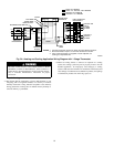
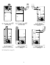
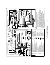
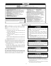
Fig. 37—Horizontal Right Application-Vent Elbow
Right
A02069
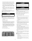
SEE NOTES: 1,2,4,7,8,9
SEE NOTES: 1,2,4,5,7,8,9
A02070
Fig. 38—Horizontal Right Application-Vent Elbow Left
then Up
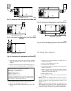
Venting Notes for Fig. 26-38
1. For common vent, vent connector sizing and vent material: United
States, latest edition of the National Fuel Gas Code (NFGC), ANSI
Z223.1/NFPA 54. In Canada, latest edition of the National Standards
of Canada, Natural Gas and Propane Installation Code (NSCNGPIC),
CSA B149.1-00.
2. Immediately increase to 5–inch vent connector outside furnace
casing when 5-inch vent connector required, refer to Note 1 above.
3. Side outlet vent for upflow and downflow installations must use
Type B vent immediately after exiting the furnace, except when
KGAVG0101DFG is used in the downflow position.
4. Type B vent where required, refer to Note 1 above.
5. 4” single wall (26 ga. min.) vent must be used inside furnace casing
and when the KGAVG0101DFG Downflow Vent Guard Kit is used
external to the furnace.
6. Accessory Downflow Vent Guard Kit, KGAVG0101DFG required
in downflow installations with bottom vent configuration.
7. Chimney Adapter Kit required for exterior masonry chimney
applications. Refer to Chimney Adapter Kit, KGACA02014FC and
KGACA02015FC for sizing and complete application details.
8. Secure vent connector to furnace elbow with (2) corrosion-resistant
sheet metal screws, spaced approximately 180° apart.
9. Secure all other single wall vent connector joints with (3) corrosion
resistant screws spaced approximately 120° apart. Secure Type B vent
connectors per vent connector manufacturer’s recommendations.
26