


NOTE: If TEST/TWIN to COM-24V terminals are jumpered
longer than 2 sec, LED will flash rapidly, and test request will be
ignored.
6. Component Test will function as follows:
a. LED flashes a status code 4 times. Record this status code
for further troubleshooting.
b. Inducer motor starts and continues to run until step f of
component test sequence.
c. Hot surface igniter is energized for 15 sec, then de-
energized.
d. Blower operates at HEAT speed for 10 sec, then turns off.
e. Blower operates at COOL speed for 10 sec, then turns off.
f. Inducer motor turns off.
Items a through f above will assist in furnace troubleshooting since
all components are functionally operated except the gas valve. This
procedure is also referred to as ″Component Test Sequence.″
7. Check LED status. If no previous fault is in history, control
will flash status code 11.
8. If LED status indicates proper operation, RELEASE
BLOWER ACCESS DOOR SWITCH, reattach wire to ″R″
terminal on furnace control board, replace blower access door,
and replace burner access door.
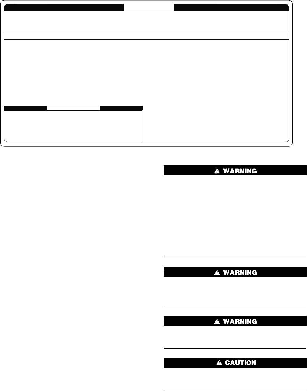
Step 2—Care and Maintenance
For continuing high performance and to minimize possible equip-
ment failure, periodic maintenance must be performed on this
equipment. Consult your local dealer about proper frequency of
maintenance and the availability of a maintenance contract.
Never store anything on, near, or in contact with the furnace,
such as:
1. Spray or aerosol cans, rags, brooms, dust mops, vacuum
cleaners, or other cleaning tools.
2. Soap powders, bleaches, waxes or other cleaning com-
pounds, plastic or plastic containers, gasoline, kerosene,
cigarette lighter fluid, dry cleaning fluids, or other volatile
fluids.
3. Paint thinners and other painting compounds, paper bags,
or other paper products.
A failure to follow this warning could result in corrosion of
the heat exchanger, fire, personal injury, or death.
Turn off the gas and electrical supplies to the unit before
performing any maintenance or service. Follow the operating
instructions on the label attached to the furnace. A failure to
follow this warning could result in personal injury.
Never operate unit without a filter or with filter access door
removed. A failure to follow this warning could result in fire,
personal injury, or death.
Personal injury can result from sharp metal edges, etc. Be
careful when removing parts. Gloves and safety glasses
should be worn when servicing equipment
The minimum maintenance on this equipment is as follows:
1. Check and clean air filter each month or more frequently if
required. Replace if torn.
2. Check blower motor and wheel for cleanliness each heating
and cooling season. Clean as necessary.
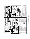
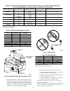
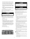
Fig. 43—Service Label
A02027
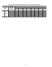
To initiate the component test sequence, shut OFF the room thermostat or disconnect the "R"
thermostat lead. Briefly short the TEST/TWIN terminal to the "Com 24V" terminal. Status LED
will flash code and then turn ON the inducer motor. The inducer motor will run for the entire
component test. The hot surface ignitor, blower motor fan speed (on AMBER LED boards
only) blower motor-heat speed, and blower motor-cool speed will be turned ON for 10-15
seconds each. Gas Valve and Humidifier will not be turned on.
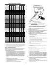
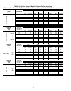
CONTINUOUS OFF - Check for 115VAC at L1 and L2, and 24VAC at SEC-1 and SEC-2.
CONTINUOUS ON - Control has 24VAC power.
RAPID FLASHING - Line voltage (115VAC) polarity reversed. If twinned, refer to twinning kit instructions.
LED CODE
STATUS
11 NO PREVIOUS CODE - Stored status code is erased automatically after 72 hours. On
RED LED boards stored status codes can also be erased when power
(115 VAC or 24 VAC) to control is interrupted.
12 BLOWER ON AFTER POWER UP (115 VAC or 24 VAC) -Blower runs for 90 seconds,
if unit is powered up during a call for heat (R-W closed) or R-W opens during blower
on-delay.
13 LIMIT CIRCUIT LOCKOUT - Lockout occurs if the limit, draft safeguard, flame rollout, or
blocked vent switch (if used) is open longer than 3 minutes or 10 successive limit trips
occurred during high-heat. - Control will auto reset after three hours. - Refer to #33.
14 IGNITION LOCKOUT - Control will auto-reset after three hours. Refer to #34.
21 GAS HEATING LOCKOUT - Control will NOT auto reset.
Check for: - Mis-wired gas valve -Defective control (valve relay)
22 ABNORMAL FLAME-PROVING SIGNAL - Flame is proved while gas valve is de-
energized. Inducer will run until fault is cleared. Check for: - Leaky gas valve
- Stuck-open gas valve
23 PRESSURE SWITCH DID NOT OPEN Check for:
- Obstructed pressure tubing. - Pressure switch stuck closed.
24 SECONDARY VOLTAGE FUSE IS OPEN Check for:
- Short circuit in secondary voltage (24VAC) wiring.
If status code recall is needed, briefly remove then reconnect one main limit wire to display stored status code. On RED LED boards do not remove power or blower door before initiating status code recall. After
status code recall is completed component test will occur.
327596-101 REV. A
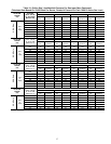
31 PRESSURE SWITCH DID NOT CLOSE OR REOPENED - If open longer than five minutes,
inducer shuts off for 15 minutes before retry. Check for: - Excessive wind
- Proper vent sizing - Defective inducer motor
- Low inducer voltage (115VAC) - Defective pressure switch
- Inadequate combustion air supply - Disconnected or obstructed pressure tubing
- Low inlet gas pressure (if LGPS used) - Restricted vent
If it opens during blower on-delay period, blower will come on for the selected blower
off-delay.
33 LIMIT CIRCUIT FAULT - Indicates the limit, draft safeguard, flame rollout, or blocked vent
switch (if used) is open or the furnace is operating in high-heat only mode due to 2
successive low heat limit trips. Blower will run for 4 minutes or until open switch remakes
whichever is longer. If open longer than 3 minutes, code changes to lockout #13.
If open less than 3 minutes status code #33 continues to flash until blower shuts off.
Flame rollout switch and BVSS require manual reset. Check for: - Restricted vent
- Proper vent sizing - Loose blower wheel. - Excessive wind
- Dirty filter or restricted duct system.
- Defective blower motor or capacitor. - Defective switch or connections.
- Inadequate combustion air supply (Flame Roll-out Switch open).
34 IGNITION PROVING FAILURE - Control will try three more times before lockout #14
occurs. If flame signal lost during blower on-delay period, blower will come on for the
selected blower off-delay. Check for: - Flame sensor must not be grounded
- Oxide buildup on flame sensor (clean with fine steel wool).
- Proper flame sense microamps (.5 microamps D.C. min., 4.0 - 6.0 nominal).
- Gas valve defective or gas valve turned off - Manual valve shut-off
- Defective Hot Surface Ignitor - Control ground continuity
- Low inlet gas pressure - Inadequate flame carryover or rough ignition
- Green/Yellow wire MUST be connected to furnace sheet metal
45 CONTROL CIRCUITRY LOCKOUT Auto-reset after one hour lockout due to;
- Gas valve relay stuck open - Flame sense circuit failure - Software check error
Reset power to clear lockout. Replace control if status code repeats.
SERVICE
COMPONENT TEST
EACH OF THE FOLLOWING STATUS CODES IS A TWO DIGIT NUMBER WITH THE FIRST DIGIT DETERMINED BY THE NUMBER OF SHORT FLASHES AND THE SECOND DIGIT BY THE NUMBER OF LONG FLASHES.
31
→