


Downflow Furnaces
Connect supply-air duct to supply-air opening on furnace. The
supply-air duct attachment must ONLY be connected to furnace
supply/outlet or air conditioning coil casing (when used). When
installed on combustible material, supply-air duct attachment must
ONLY be connected to the accessory subbase, KGASB0201ALL,
or factory approved air conditioning coil casing. DO NOT cut
main furnace casing to attach supply side air duct, humidifier, or
other accessories. All accessories MUST be connected external to
furnace casing.
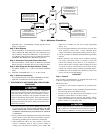
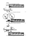
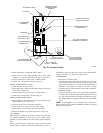
RETURN AIR CONNECTIONS
Never connect return-air ducts to the back of the furnace. A
failure to follow this warning can cause a fire, personal injury,
or death.
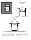
Downflow Furnaces
The return-air duct must be connected to return-air opening
(bottom inlet) as shown in Fig. 1. DO NOT cut into casing sides
(left or right). Side opening is permitted for only upflow and most
horizontal furnaces. Bypass humidifier connections should be
made at ductwork or coil casing sides exterior to furnace.
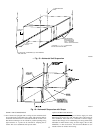
Upflow and Horizontal Furnaces
The return-air duct must be connected to bottom, sides (left or
right), or a combination of bottom and side(s) of main furnace
casing as shown in Fig. 1. Bypass humidifier may be attached to
unused side return air portion of the furnace casing. (See Fig. 18,
19, and 20.)
Not all horizontal furnaces are approved for side return air
connections. (See Fig. 20.)
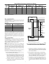
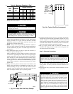
Step 6—Gas Piping
Never purge a gas line into a combustion chamber. Never test
for gas leaks with an open flame. Use a commercially
available soap solution made specifically for the detection of
leaks to check all connections. A failure to follow this
warning could result in fire, explosion, personal injury, or
death.
Gas piping must be installed in accordance with national and local
codes. Refer to current edition of NFGC in the U.S., the NSCNG-
PIC in Canada.
Installations must be made in accordance with all authorities
having jurisdiction. If possible, the gas supply line should be a
separate line running directly from meter to furnace.
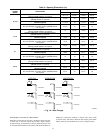
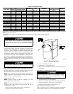
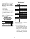
Refer to Table 4 for recommended gas pipe sizing. Risers must be
used to connect to furnace and to meter. Support all gas piping
with appropriate straps, hangers, etc. Use a minimum of 1 hanger
every 6 ft. Joint compound (pipe dope) should be applied sparingly
and only to male threads of joints. Pipe dope must be resistant to
the action of propane gas.
If local codes allow the use of a flexible gas appliance
connector, always use a new listed connector. Do not use a
connector which has previously serviced another gas appli-
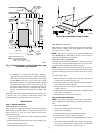
ance. Black iron pipe shall be installed at the gas valve and
extend a minimum of 2-in. outside the furnace.
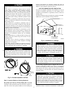
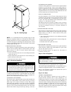
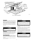
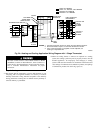
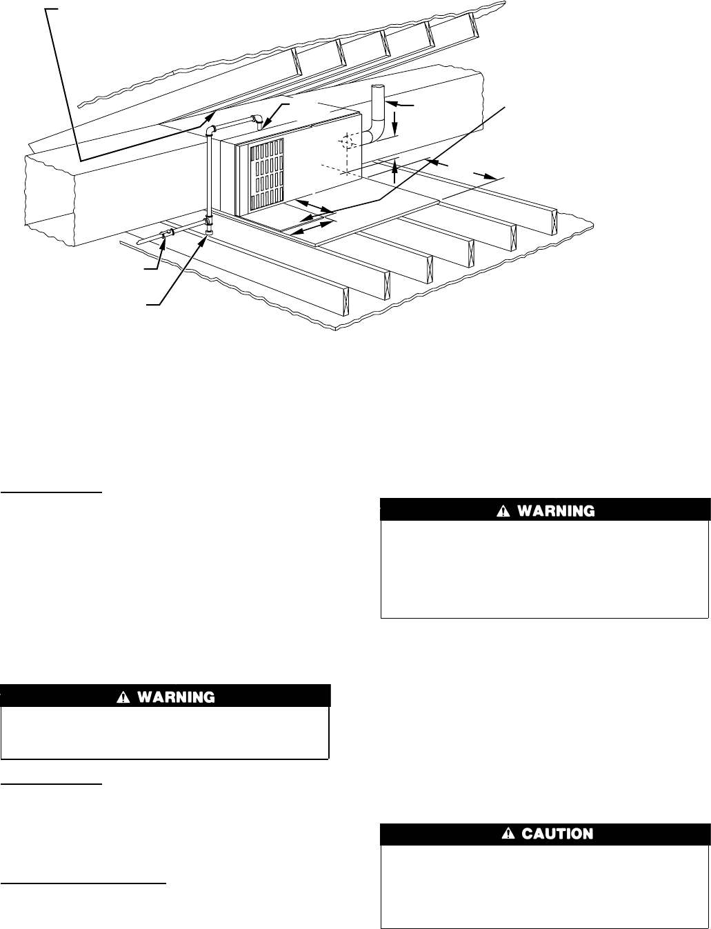
Fig. 17—Typical Attic Installation
A02164
30-IN. MIN
WORK AREA
6″
MIN*
TYPE-B
VENT
17
3
/4
″
22
″
SHEET
METAL
SEDIMENT
TRAP
MANUAL SHUTOFF
GAS VALVE
LINE CONTACT ONLY PERMISSIBLE BETWEEN
LINES FORMED BY INTERSECTIONS OF
THE TOP AND TWO SIDES OF THE FURNACE
JACKET AND BUILDING JOISTS,
STUDS, OR FRAMING.
GAS
ENTRY
17
3
/4
″ OVER ALL
4
3
/4
″ UNDER DOOR
1″ UNDER FURNACE
EXTEND OUT 12″ OUT
FROM FACE OF DOOR
* WHEN USED WITH
SINGLE WALL VENT
CONNECTIONS
13
→
→