


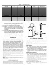
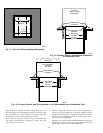
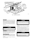
NOTE: It is recommended that the perforated supply-air duct
flanges be completely folded over or removed from furnace when
installing the furnace on a factory-supplied cased coil or coil box.
To remove the supply-air duct flange, use wide duct pliers or hand
seamers to bend flange back and forth until it breaks off. Be careful
of sharp edges. (See Fig. 14.)
BOTTOM RETURN AIR INLET
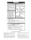
These furnaces are shipped with bottom closure panel installed in
bottom return-air opening. Remove and discard this panel when
bottom return air is used. To remove bottom closure panel,
perform the following:
1. Tilt or raise furnace and remove 2 screws holding bottom filler
panel. (See Fig. 9.)
2. Rotate bottom filler panel downward to release holding tabs.
3. Remove bottom closure panel.
4. Reinstall bottom filler panel and screws.
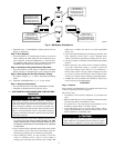
Step 3—Horizontal Installation
Do not install the furnace on its back or hang furnace with
control compartment facing downward. Safety control opera-
tion will be adversely affected. Never connect return-air ducts
to the back of the furnace. Failure to follow this warning
could result in fire, personal injury, or death.
The furnace can be installed horizontally in an attic or crawl space
on either the left-hand (LH) or right-hand (RH) side. The furnace
can be hung from floor joists, rafters or trusses or installed on a
platform, non-combustible blocks, bricks or pad.
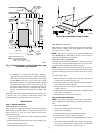
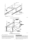
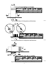
SUSPENDED UNIT SUPPORT
The furnace may be supported under each end with threaded rod,
angle iron or metal plumber’s strap as shown. (See Fig. 15 and 16.)
Secure angle iron to bottom of furnace as shown. Heavy-gauge
sheet metal straps (plumber’s straps) may be used to suspend the
unit from each bottom corner. To prevent screws from pulling out,
use2#8x¾-in. screw into the side and2#8x¾-in. screw in the
bottom of the furnace casing for each strap. (See Fig. 15 and 16.)
PLATFORM UNIT SUPPORT
Construct working platform at location where all required furnace
clearances are met. (See Fig. 2 and 17.) For furnaces with 1-in.
clearance requirement on side, set unit on non-combustible blocks,
bricks or angle iron. For crawlspace installations, if the unit is not
suspended from the floor joists, the ground underneath unit must
be level and the unit set on blocks or bricks.
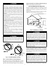
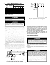
ROLL-OUT PROTECTION
Provide a minimum 17 3/4″ X22″ piece of sheet metal for roll-out
protection in front of burner area for units closer than 12 inches
above the combustible deck or suspended units closer than 12-in.
to joists. The sheet metal MUST extend underneath the furnace
casing by 1 in. with the door removed.
The bottom closure pan on furnaces of widths 17 1/2 in. and larger
may be used for roll-out protection when bottom of furnace is used
for return air connection. See Fig. 17 for proper orientation of
roll-out shield.
BOTTOM RETURN AIR INLET
These furnaces are shipped with bottom closure panel installed in
bottom return-air opening. Remove and discard this panel when
bottom return air is used. To remove bottom closure panel,
perform the following:
1. Tilt or raise furnace and remove 2 screws holding bottom filler
panel. (See Fig. 9.)
2. Rotate bottom filler panel downward to release holding tabs.
3. Remove bottom closure panel.
4. Reinstall bottom filler panel and screws.
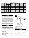
SIDE RETURN AIR INLET
These furnaces are shipped with bottom closure panel installed in
bottom return-air opening. This panel MUST be in place when
only one side return air is used.
Not all horizontal furnaces are approved for side return air
connections (See Fig. 20.)
Step 4—Filter Arrangement
Never operate a furnace without a filter or with filter access
door removed. Failure to follow this warning could result in
fire, personal injury, or death.
There are no provisions for an internal filter rack in these furnaces.
A field-supplied accessory external filter rack is required.
This furnace requires KGAFR0301ALL 1″ external filter rack or a
suitable field-supplied substitute, such as the Media Cabinet.
Refer to the instructions supplied with external filter rack for
assembly and installation options.
Step 5—Air Ducts
GENERAL REQUIREMENTS
The duct system should be designed and sized according to
accepted national standards such as those published by: Air
Conditioning Contractors Association (ACCA), Sheet Metal and
Air Conditioning Contractors National Association (SMACNA) or
American Society of Heating, Refrigerating and Air Conditioning
Engineers (ASHRAE) or consult The Air Systems Design Guide-
lines reference tables available from your local distributor. The
duct system should be sized to handle the required system design
CFM at the design external static pressure.
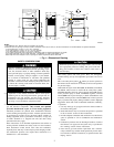
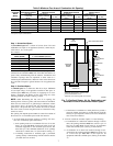
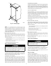
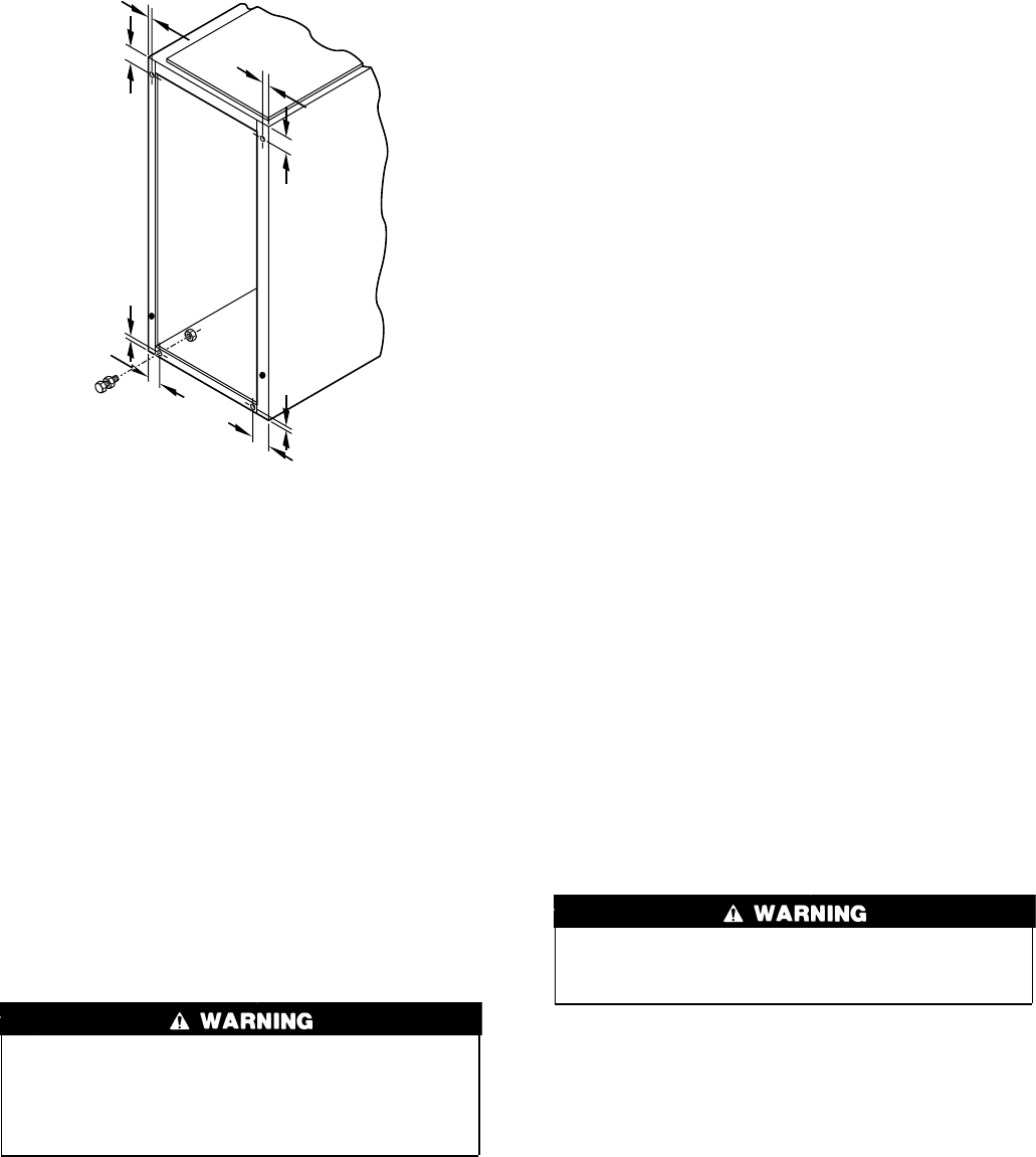
Fig. 10—Leveling Legs
A02071
1
3
⁄4″
1
3
⁄4″
1
3
⁄4″
1
3
⁄4″
5
⁄16″
5
⁄16″
5
⁄16″
5
⁄16″
9
→
→
→
→