


Personal injury can result form sharp metal edges, etc. Be
careful when removing parts. Gloves and safety glasses
should be worn when servicing equipment.
1. Maintain 115-v wiring and ground. Improper polarity will
result in rapid flashing LED and no furnace operation.
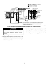
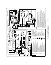
2. Make thermostat wire connections at the 24-v terminal block
on the furance control. Failure to make proper connections
will result in improper operation. (See Fig. 24.)
3. Gas supply pressure to the furnace must be greater than 4.5-in.
wc (0.16 psig) but not exceed 14-in. wc (0.5 psig).
4. Check all manual-reset switches for continuity.
5. Install blower compartment door. Door must be in place to
operate furnace.
6. Replace outer door.
Step 2—Start-Up Procedures
Never purge a gas line into a combustion chamber. Never use
matches, candles, flame, or other sources of ignition for the
purpose of checking leakage. Use a soap-and-water solution
to check for leakage. Failure to follow this warning can cause
fire, explosion, personal injury, or death.
1. Purge gas lines after all connections have been made.
2. Check gas lines for leaks.
Blower access door switch opens 115-v power to control. No
component operation can occur unless switch is closed.
Caution must be taken when manually closing this switch for
service purposes. Failure to follow this warning could result
in electrical shock, personal injury, or death.
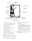
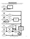
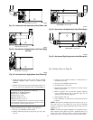
3. To Begin Component Self-Test: Disconnect the thermostat R
lead from furnace control board. Manually close the blower
door switch. Briefly short the TEST/TWIN terminal to the
C
OM 24V terminal until LED goes out. Remove jumper from
terminals. (See Fig. 23.)
NOTE: The furnace control allows all components, except the gas
valve, to be run for short period of time. This feature helps
diagnose a system problem in case of a component failure.
Component test feature will not operate if any thermostat signal is
present at the control.
Component test sequence is as follows:
Refer to service label attached to furnace or see Fig. 43.
a. LED will display previous status code 4 times.
b. Inducer motor starts and continues to run until Step f of
component test sequence.
c. Hot surface ignitor is energized for 15 sec., then off.
d. Blower motor operates on HEAT speed for 10 sec.
e. Blower motor operates on COOL speed for 10 sec.
f. Inducer motor stops.
g. Reconnect R lead to furnace control board, release blower
door switch and re-install blower door.
4. Operate furnace per instruction on door.
5. Verify furnace shut down by lowering thermostat setting
below room temperature.
6. Verify furnace restarts by raising thermostat setting above
room temperature.
Step 3—Adjustments
DO NOT bottom out gas valve regulator adjusting screw.
This can result in unregulated manifold pressure and result in
excess overfire and heat exchanger failures.
DO NOT redrill orifices. Improper drilling (burrs, out-of-
round holes, etc.) can cause excessive burner noise and
misdirection of burner flames. This can result in flame
impingement of heat exchangers, causing failures. (See Fig.
41.)
Furnace gas input rate on rating plate is for installations at altitudes
up to 2000 ft. Furnace input rate must be within ±2 percent of
furnace rating plate input.
In the U.S.A., the input rating for altitudes above 2,000 ft. must be
reduced by 4 percent for each 1,000 ft. above sea level. In Canada,
input rating must be reduced by 10 percent for altitudes of 2,000
ft. to 4,500 ft. above sea level.
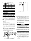
1. Determine the correct gas input rate.
In the U.S.:
For installations below 2000 ft., refer to the unit rating plate.
For installations above 2000 ft., multiply the input on the
rating plate by the de-rate multiplier in Table 6 for the correct
input rate.
In Canada:
At installation altitudes from 2000 to 4500 ft, this furnace must be
derated 10 percent by an authorized Gas Conversion Station or
Dealer. To determine correct input rate for altitude, see example 1
and use 0.90 as derate multiplier factor.
EXAMPLE 1:
88,000 BTUH INPUT FURNACE INSTALLED AT 4300 FT.
Derate Furnace Input Rate
Furnace Input Rate X Multiplier = at Installation
at Sea Level Factor Altitude
88,000 X 0.90 = 79,200
2. Determine the correct orifice and manifold pressure adjust-
ment. There are two different orifice and manifold adjustment
tables.
All models in all positions, except Low NOx models in
downflow or horizontal positions, use Table 10 (22,000
BTUH/Burner)
Low NOx models in the downflow or horizontal positions
must use Table 11 (21,000BTUH/Burner). See input listed on
furnace rating plate.
a. Obtain average yearly gas heat value (at installed altitude)
from local gas supplier.
b. Obtain average yearly gas specific gravity from local gas
supplier.
c. Find installation altitude in Table 10 or 11.
d. Find closest natural gas heat value and specific gravity in
Table 10 or 11.
e. Follow heat value and specific gravity lines to point of
intersection to find orifice size and manifold pressure
settings for proper operation.
23
→