


9. Using field-provided 25-caliber rifle cleaning brush, 1/4″
diameter steel spring cable, 36 in. long, a variable speed,
reversible electric drill, and vacuum cleaner, clean cells as
follows:
a. Remove metal screw fitting from wire brush to allow
insertion into cable.
b. Insert the twisted wire end of brush into end of spring
cable, and crimp tight with crimping tool or crimp by
striking with ball-peen hammer. TIGHTNESS IS VERY
IMPORTANT.
NOTE: The materials needed in item 9 can usually be purchased
at local hardware stores.
(1.) Attach variable-speed, reversible drill to the end of
spring cable (end opposite brush).
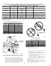
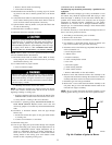
(2.) Insert brush end of cable into the outlet opening of cell
and slowly rotate with drill. DO NOT force cable.
Gradually insert cable into upper pass of cell. (See Fig.
46.)
(3.) Work cable in and out of cell 3 or 4 times to obtain
sufficient cleaning. DO NOT pull cable with great
force. Reverse drill and gradually work cable out.
(4.) Insert brush end of cable in burner inlet opening of
cell, and proceed to clean 2 lower passes of cell in
same manner as upper pass.
(5.) Repeat foregoing procedures until each cell in furnace
has been cleaned.
(6.) Using vacuum cleaner, remove residue from each cell.
(7.) Using vacuum cleaner with soft brush attachment,
clean burner assembly.
(8.) Clean flame sensor with fine steel wool.
(9.) Reinstall burner assembly. Center burners in cell
openings.
10. Remove old sealant from cell panel and inducer backing plate
flange.
11. Spray releasing agent on the heat exchanger cell panel where
collector box assembly contacts cell panel.
NOTE: A releasing agent such as cooking spray or equivalent
(must not contain corn or canola oil, aromatic or halogenated
hydrocarbons or inadequate seal may occur) and RTV sealant
(G.E. 162, 6702, or Dow-Corning 738) are needed before starting
installation. DO NOT substitute any other type of RTV sealant.
G.E. 162 (P771-9003) is available through RCD in 3-oz tubes.
12. Apply new sealant to flange of inducer assembly and attach to
cell panel using existing screws, making sure all screws are
secure.
13. Reconnect wires to the following components (Use connection
diagram on wiring label, if wires were not marked for
reconnection locations.):
a. Draft safeguard switch.
b. Inducer motor.
c. Pressure switch(es).
d. Limit overtemperature switch.
e. Gas valve.
f. Hot surface igniter.
g. Flame-sensing electrode.
h. Flame rollout switches.
i. Install NOx baffles (if removed).
14. Reinstall internal vent pipe, if applicable.
15. Reinstall vent connector on furnace vent elbow. Securely
fasten vent connector to vent elbow with 2 field-supplied,
corrosion-resistant, sheet metal screws located 180° apart.
16. Replace blower access door only.
17. Set thermostat above room temperature and check furnace for
proper operation.
18. Verify blower airflow and speed changes between heating and
cooling.
19. Check for gas leaks.
Never use a match or other open flame to check for gas leaks.
Use a soap-and-water solution. A failure to follow this
warning could result in fire, personal injury, or death.
20. Replace outer access door.
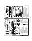
Step 3—Sequence of Operation
NOTE: Furnace control must be grounded for proper operation or
control will lock out. Control is grounded through green/yellow
wire routed to gas valve and manifold bracket screw.
Using the schematic diagram in Fig. 39, follow the sequence of
operation through the different modes. Read and follow the wiring
diagram very carefully.
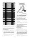
NOTE: If a power interruption occurs during a call for heat (W),
the control will start a 90-second blower-only ON period two
seconds after power is restored, if the thermostat is still calling for
gas heating. The red LED light will flash code 12 during the
90-second period, after which the LED will be ON continuous, as
long as no faults are detected. After the 90-second period, the
furnace will respond to the thermostat normally.
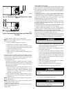
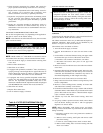
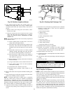
Fig. 45—Position of Igniter to Burner
A02151
7/8”
Fig. 46—Cleaning Heat Exchanger Cell
A91252
34
→