


1. Route listed power cord through hole in J-Box.
2. Secure power cord to J-Box bracket with a strain relief
bushing or a connector approved for the type of cord used.
3. Secure ground wire to green screw on J-Box bracket.
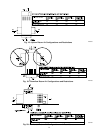
4. Connect line voltage leads as shown in Fig. 24.
FOR BX CABLE INSTALLATION
1. Route BX cable to hole in J-Box.
2. Secure BX cable to J-Box bracket with connectors approved
for the type of cable used.
3. Secure ground wire to green screw on J-Box bracket.
4. Connect line voltage leads as shown in Fig. 24.
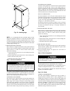
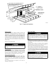
J-BOX COVER INSTALLATION
1. Remove J-Box cover from blower access door on furnace and
reinstall blower access door screw.
2. Fold tab on J-box cover to bracket with pliers.
3. Insert tab of J-box cover into slot of J-box bracket.
4. Secure J-Box cover to bracket with screw provided.
5. Remove U-shaped cut-out from outer door to clear J-box.
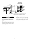
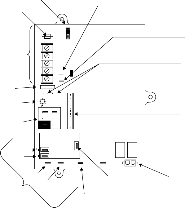
24-V WIRING
Make field 24-v connections at the 24-v terminal strip. (See Fig.
23.) Connect terminal Y as shown in Fig. 24 for proper cooling
operation. Use only AWG No. 18, color-coded, copper thermostat
wire.
The 24-v circuit contains an automotive-type, 3-amp fuse located
on the control. Any direct shorts during installation, service, or
maintenance could cause this fuse to blow. If fuse replacement is
required, use ONLY a 3-amp fuse of identical size.
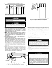
ACCESSORIES
1. Electronic Air Cleaner (EAC)
Connect an accessory Electronic Air Cleaner (if used) using
1/4-in female quick connect terminals to the two male 1/4-in
quick-connect terminals on the control board marked EAC-1
and EAC-2. The terminals are rated for 115 VAC, 1.0 amps
maximum and are energized during blower motor operation.
2. Humidifier (HUM)
Connect an accessory 24 VAC, 0.5 amp maximum humidifier
(if used) to the 1/4-in male quick-connect HUM terminal and
C
OM-24V screw terminal on the control board thermostat strip.
The HUM terminal is energized when pressure switch (PRS)
closes.
NOTE: A field-supplied, 115-v controlled relay connected to
EAC terminals may be added if humidifier operation is desired
during blower operation.
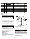
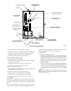
Fig. 23—Furnace Control
A02100
BLW
NUETRAL
STATUS CODE LED
SEC-2 SEC-1
EAC-2 L2
FUSE 3-AMP
0.5 AMP@24VAC
HUM
TEST/TWIN
G Com W Y R
24V
120 180
90 150
BLOWER OFF-DELAY
PLT 1
COOL HEAT
SPARE-1 SPARE-2
EAC-1
1-AMP@
115VAC
PR-1
L1
PL2 1
24-V THERMOSTAT
TERMINALS
3-AMP FUSE
LED OPERATION &
DIAGNOSTIC LIGHT
115-VAC(L2)NEUTRAL
CONNECTIONS
COOL
HEAT
SPARE-1
SPARE-2
BLOWER SPEED
SELECTION TERMINALS
EAC-1 TERMINAL
(115-VAC 1.0 AMP MAX.)
115 VAC (L1) LINE
VOLTAGE CONNECTION
PL2-HOT SURFACE
IGNITER & INDUCER
MOTOR CONNECTOR
PL1-LOW VOLTAGE MAIN
HARNESS CONNECTOR
TRANSFORMER 24-VAC
CONNECTIONS
HUMIDIFIER TERMINAL
(24-VAC 0.5 AMP MAX.)
TWINNING AND/OR
COMPONENT TEST
TERMINAL
BLOWER OFF-DELAY
J2
J2 JUMPER
PLT
17