


Connect gas pipe to gas valve using a backup wrench to avoid
damaging gas controls.
Use proper length of pipe to avoid stress on gas control
manifold. Failure to follow this warning could result in a gas
leak resulting in fire, explosion, personal injury, or death.
An accessible manual shutoff valve MUST be installed external to
furnace casing and within 6 ft of furnace. A 1/8-in. NPT plugged
tapping, accessible for test gage connection, MUST be installed
immediately upstream of gas supply connection to furnace and
downstream of manual shutoff valve.
NOTE: The gas valve inlet pressure tap connection is suitable to
use as test gage connection providing test pressure DOES NOT
exceed maximum 0.5 psig (14-in. wc) stated on gas control valve.
(See Fig. 50.)
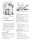
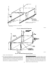
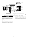
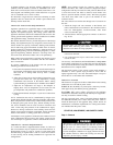
Some installations require gas entry on right side of furnace (as
viewed in upflow). (See Fig. 21a.)
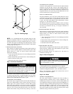
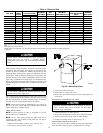
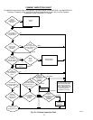
Install a sediment trap in riser leading to furnace as shown in Fig
21b. Connect a capped nipple into lower end of tee. Capped nipple
should extend below level of gas controls. Place a ground joint
union between gas control manifold and exterior manual equip-
ment gas shutoff valve. A 1/8-in. NPT plugged tapping, accessible
for test gage connection, MUST be installed immediately upstream
of gas supply connection to furnace and downstream of manual
shutoff valve.
Piping should be pressure and leak tested in accordance with
NFGC in the United States or NSCNGPIC in Canada, local, and
national plumbing and gas codes before the furnace has been
connected. After all connections have been made, purge lines and
check for leakage at furnace prior to operating furnace.
If pressure exceeds 0.5 psig (14-in. wc), gas supply pipe must be
disconnected from furnace and capped before pressure test. If test
pressure is equal to or less than 0.5 psig (14-in. wc), turn off
electric shutoff switch located on furnace gas control valve and
accessible manual shutoff valve before test. After all connections
have been made, purge lines and check for leakage.
The gas supply pressure shall be within the maximum and
minimum inlet supply pressures marked on the rating plate with
the furnace burners ON and OFF.
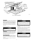
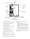
Step 7—Electrical Connections
Blower access panel door switch opens 115-v power to
control center. No component operation can occur. Do not
bypass or close switch with panel removed. Failure to follow
this warning could result in personal injury or death.
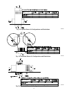
See Fig. 24 for field wiring diagram showing typical field 115-v
wiring. Check all factory and field electrical connections for
tightness.
Field-supplied wiring shall conform with the limitations of 63°F
(33°C) rise.
The cabinet MUST have an uninterrupted or unbroken ground
according to NEC ANSI/NFPA 70-2002 and Canadian Elec-
trical Code CSA C22.1 or local codes to minimize personal
injury if an electrical fault should occur. This may consist of
electrical wire, conduit approved for electrical ground or a
listed, grounded power cord (where permitted by local code)
when installed in accordance with existing electrical codes.
Refer to the power cord manufacturer’s ratings for proper
wire gage. Do not use gas piping as an electrical ground.
Failure to follow this warning could result in electrical shock,
fire, or death.
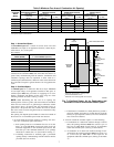
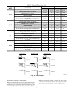
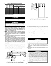
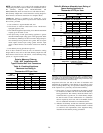
Table 4—Maximum Capacity of Pipe*
NOMINAL
IRON
PIPE
SIZE
(IN.)
INTERNAL
DIAMETER
(IN.)
LENGTH OF PIPE (FT)
10 20 30 40 50
1/2 0.622 175 120 97 82 73
3/4 0.824 360 250 200 170 151
1 1.049 680 465 375 320 285
1-1/4 1.380 1400 950 770 660 580
1-1/2 1.610 2100 1460 1180 990 900
* Cubic ft of gas per hr for gas pressures of 0.5 psig (14–in. wc) or less and a
pressure drop of 0.5–in wc (based on a 0.60 specific gravity gas).
Ref: Table 12.2 NFPA 54-2002.
→ Fig. 21a—Right Side Gas Entry Example
A02327
90° Elbow
2" Nipple
Street Elbow
Gas Valve
Fig. 21b—Typical Gas Pipe Arrangement
A02035
UNION
SEDIMENT
TRAP
MANUAL
SHUTOFF
VALVE
(REQUIRED
GAS
SUPPLY
15
→
→
→
→
→
→
→
→