


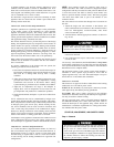

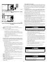
a. Mechanical thermostat—Set thermostat heat anticipator to
match the amp draw of the electrical components in the
R-W circuit. Accurate amp draw readings can be obtained
at the wires normally connected to thermostat subbase
terminals, R and W. The thermostat anticipator should
NOT be in the circuit while measuring current.
(1.) Remove thermostat from subbase or from wall.
(2.) Connect an amp meter as shown in Fig. 42 across the
R and W terminals or R and W wires.
(3.) Record amp draw across terminals when furnace is in
heating and after blower starts.
(4.) Set heat anticapator on thermostat per thermostat
instructions and install on subbase or wall.
b. Electronic thermostat: Set cycle rate for 4 cycles per hr.
7. Adjust blower off delay
The blower off delay has 4 adjustable settings from 90 sec to
180 sec. The blower off delay jumpers are located on the
furnace control board. (See Fig. 23.)
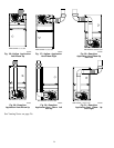
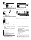
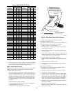
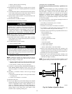
Caution!! For the following applications, use the minimum vertical vent sections as specified below.
For all other applications, follow exclusively the National Fuel Gas Code.
FURNACE ORIENTATION VENT ORIENTATION FURNACE INPUT(BTU/HR)
MINIMUM
VENT DIAMETER (IN.)*
MINIMUM VERTICAL VENT HEIGHT (FT)**
Downflow
Vent elbow left, then up
Fig. 30
154,000
132,000
110,000(036/-12 only)
512
Horizontal Left
Vent elbow right,
then up
Fig. 33
154,000
132,000
57
Horizontal Left
Vent Elbow up
Fig. 34
154,000
132,000
57
Horizontal Left
Vent elbow right
Fig. 35
154,000 5 7
Downflow
Vent elbow up then left
Fig. 28
110,000
(036/-12 only)
510
Downflow
Vent elbow up, then right
Fig. 31
110,000
(036/-12 only)
510
NOTE: All vent configurations must also meet National Fuel Gas Code venting requirements NFGC.
*4 in. inside casing or vent guard
**Including 4 in. vent section(s)
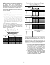
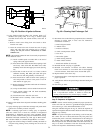
Table 6–Altitude Derate Multipler for U.S.A.
ALTITUDE
(FT)
PERCENT
OF DERATE
DERATE MULTIPLIER
FACTOR*
0–2000 0 1.00
2001–3000 8–12 0.90
3001–4000 12–16 0.86
4001–5000 16–20 0.82
5001–6000 20–24 0.78
6001–7000 24–28 0.74
7001–8000 28–32 0.70
8001–9000 32–36 0.66
9001–10,000 36–40 0.62
* Derate multiplier factors are based on midpoint altitude for altitude range.
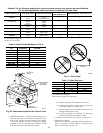
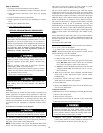
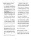
Fig. 40—Redundant Automatic Gas Control Valve
A00157
ON AND OFF
SWITCH
GAS PRESSURE
REGULATOR
ADJUSTMENT
MANIFOLD
PRESSURE TAP
INLET
PRESSURE
TAP
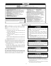
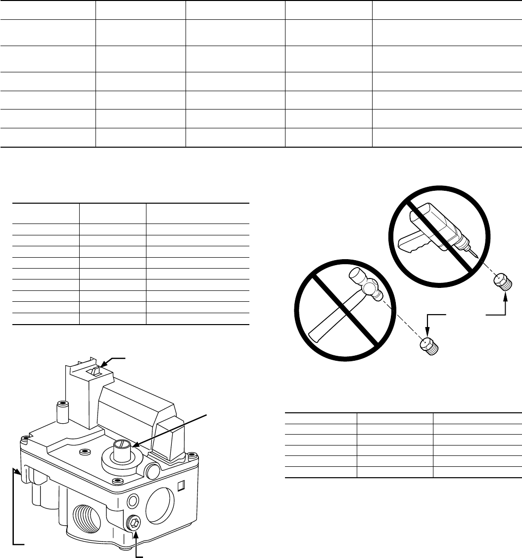
Fig. 41—Orifice Hole
A93059
BURNER
ORIFICE
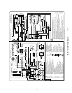
Table 7—Speed Selection
COLOR SPEED AS SHIPPED
White Common BLW
Black High COOL
Yellow† Med-High SPARE
Blue* Med-Low SPARE
Red* Low HEAT
* 1/5 HP motor models: BLUE to HEAT, RED to SPARE.
† Not available on 1/5 HP motors.
NOTE: Continuous blower is the HEAT speed.
28