


DO NOT connect furnace control HUM terminal to HUM
(humidifier) terminal on Thermidistat™, Zone Controller or
similar device. See Thermidistat™, Zone Controller, thermo-
stat, or controller manufacturer’s instructions for proper
connection.
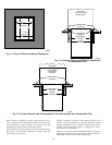
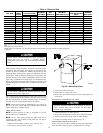
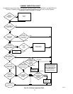
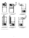
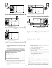
Step 8—Venting
The furnace shall be connected to a factory built chimney or vent
complying with a recognized standard, or a masonry or concrete
chimney lined with a lining material acceptable to the authority
having jurisdiction. Venting into an unlined masonry chimney or
concrete chimney is prohibited.
When an existing furnace is removed or replaced in a venting
system, the venting system may not be properly sized to vent the
attached appliances. An improperly sized Category I venting
system could cause the formation of condensate in the furnace and
vent, leakage of condensate and combustion products, and spillage
of combustion products into the living space, etc.
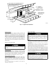
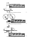
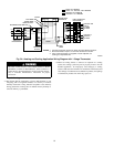
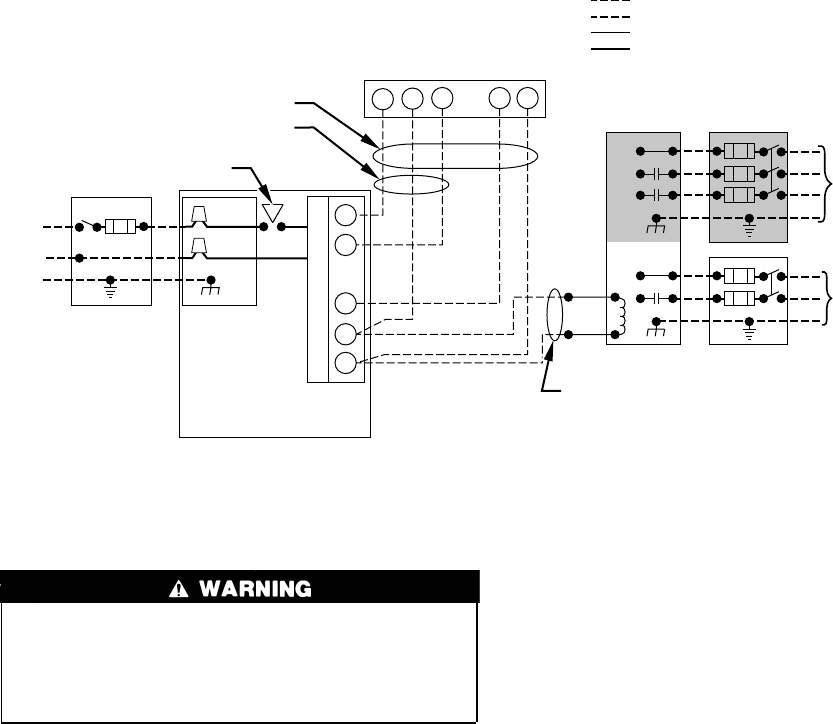
Fig. 24—Heating and Cooling Application Wiring Diagram with 1–Stage Thermostat
A99440
115-V FIELD-
SUPPLIED
DISCONNECT
AUXILIARY
J-BOX
24-V
TERMINAL
BLOCK
THREE-WIRE
HEATING-ONLY
FIVE WIRE
NOTE 1
NOTE 2
FIELD-SUPPLIED
DISCONNECT
CONDENSING
UNIT
TWO
WIRE
FURNACE
C
O
N
T
R
O
L
R
G
COM
WCR GY
GND
GND
FIELD 24-V WIRING
FIELD 115-, 208/230-, 460-V WIRING
FACTORY 24-V WIRING
FACTORY 115-V WIRING
208/230- OR
460-V
THREE
PHASE
208/230-V
SINGLE
PHASE
BLOWER DOOR SWITCH
WHT
BLK
WHT
BLK
NOTES: Connect Y-terminal in furnace as shown for proper blower operation.
Some thermostats require a "C" terminal connection as shown.
If any of the original wire, as supplied, must be replaced, use
same type or equivalent wire.
W
Y/Y2
GND
THERMOSTAT
TERMINALS
1.
2.
3.
18
→
→