


3. Check electrical connections for tightness and controls for
proper operation each heating season. Service as necessary.
4. Inspect burner compartment before each heating season for
rust, corrosion, soot or excessive dust. If necessary, have
furnace and burner serviced by a qualified professional.
5. Inspect the vent pipe/vent system before each heating season
for rust, corrosion, water leakage, sagging pipes or broken
fittings. Have vent pipes/vent system serviced by a qualified
professional.
6. Inspect any accessories attached to the furnace such as a
humidifier or electronic air cleaner. Perform any service or
maintenance to the accessories as recommended in the acces-
sory instructions.
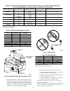
CLEANING AND/OR REPLACING AIR FILTER
The air filter arrangement may vary depending on the application.
The filter is exterior to the furnace casing.
NOTE: If the filter has an airflow direction arrow, the arrow must
point towards the blower.
Personal injury can result from sharp metal edges, etc. Be
careful when removing parts. Gloves and safety glasses
should be worn when servicing equipment
Media cabinet filter procedures:
NOTE: Media cabinet or 1″ Filter Rack are accessories and are
not included from the factory with the standard furnace model.
1. Turn off electrical supply to furnace before removing filter
access door.
2. Remove filter cabinet door.
3. Slide filter out of cabinet.
4. If equipped with permanent, washable 1″ filter, clean filter by
spraying cold tap water through filter in opposite direction of
airflow. Rinse filter and let dry. Oiling or coating of the filter
is not recommended. See Table 9 for size information.
5. If equipped with factory-specified disposable media filter,
replace only with media filter having the same part number
and size. For expandable replacement media, refer to the
instructions included with the replacement media. If equipped
with KGAFR0301ALL external filter rack, See Table 9.
6. Slide filter into cabinet.
7. Replace filter cabinet door.
8. Turn on electrical supply to furnace.
BLOWER MOTOR AND WHEEL
Blower access door switch opens 115-v power to control. No
component operation can occur unless switch is closed.
Caution must be taken when manually closing this switch for
service purposes. Failure to follow this warning could result
in personal injury or death.
The blower wheel should not be dropped or bent as balance
will be affected.
The following steps should be performed by a qualified service
technician.
To ensure long life and high efficiency, clean accumulated dirt and
grease from blower wheel and motor annually.
The inducer and blower motors are pre-lubricated and require no
additional lubrication. These motors can be identified by the
absence of oil ports on each end of the motor.
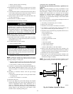
Clean blower motor and wheel as follows:
1. Turn off electrical supply to furnace.
2. Unscrew the thumbscrew on outer door and remove outer
door.
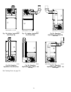
3. For downflow or horizontal furnaces having vent pipes within
the furnace that pass in from of the blower access door:
a. Disconnect vent connector from furnace vent elbow.
b. Disconnect and remove short piece of vent pipe from
within furnace.
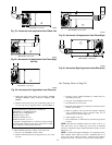
4. Remove 2 screws from blower access door and remove blower
access door.
5. Disconnect blower leads from furnace control. Note wire color
and location for reassembly. All other factory wires can be left
connected, but field thermostat connections may need to be
disconnected depending on their length and routing.
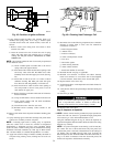
6. Remove 2 screws from control box to blower shelf.
7. Hang control box from front of furnace casing and away from
blower compartment.
8. Remove 2 screws holding blower assembly to blower deck
and slide blower assembly out of furnace.
9. Clean blower wheel and motor using a vacuum with soft brush
attachment. Blower wheel blades may be cleaned with a small
paint or flux brush. Do not remove or disturb balance weights
(clips) on blower wheel blades.
10. Vacuum any loose dust from blower housing, wheel and
motor.
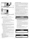
11. If a greasy residue is present on blower wheel, remove wheel
from the blower housing and wash it with an appropriate
degreaser. To remove wheel:
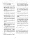
NOTE: Before disassembly, mark blower motor, and blower
housing so motor and each arm is positioned at the same location
during reassembly.
a. Disconnect capacitor wires and ground wire attached to
blower housing.
b. Remove screws securing cutoff plate and remove cutoff
plate from housing.
c. Loosen set screw holding blower wheel on motor shaft.
d. Remove bolts holding motor to blower housing and slide
motor out of wheel.
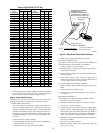
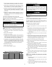
Table 9—FILTER SIZE INFORMATION (IN.)
FURNACE
CASING WIDTH
FILTER QUANTITY AND SIZE
FILTER
TYPE
Side Return Bottom Return
14-1/2 (1) 16 X 25 X 1 (1) 14 X 25 X 1 Cleanable*
17-1/2 (1) 16 X 25 X 1 (1) 16 X 25 X 1 Cleanable*
21 (1) 16 X 25 X 1 (1) 20 X 25 X 1 Cleanable*
24** (1) 16 X 25 X 1 (1) 24 X 25 X 1 Cleanable*
* Recommended
** Some furnaces may have 2 filters
32
→