


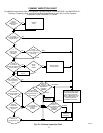

Step 5—Checklist
1. Put away tools and instruments. Clean up debris.
2. Check that blower OFF-DELAY time is selected as desired.
3. Verify that blower and burner access doors are properly
installed.
4. Cycle test furnace with room thermostat.
5. Check operation of accessories per manufacturer’s instruc-
tions.
6. Review User’s Guide with owner.
7. Leave literature packet near furnace.
SERVICE AND MAINTENANCE PROCEDURES
The ability to properly perform maintenance on this equip-
ment requires certain knowledge, mechanical skills, tools, and
equipment. If you do not possess these, do not attempt to
perform any maintenance on this equipment other than those
procedures recommended in the User’s Manual. FAILURE
TO FOLLOW THIS WARNING COULD RESULT IN
POSSIBLE DAMAGE TO THIS EQUIPMENT, SERIOUS
PERSONAL INJURY, OR DEATH.
ELECTRICAL SHOCK, FIRE, OR EXPLOSION HAZARD
Failure to follow safety warnings exactly could result in
dangerous operation, serious injury, death, or property dam-
age.
Improper servicing could result in dangerous operation,
serious injury, death, or property damage.
- Before servicing, disconnect all electrical power to furnace.
- When servicing controls, label all wires prior to disconnect-
ing. Reconnect wires correctly.
- Verify proper operation after servicing.
Label all wires prior to disconnection when servicing con-
trols. Wiring errors can cause improper and dangerous
operation.
Step 1—Introduction
GENERAL
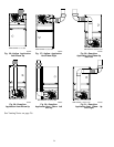
These instructions are written as if the furnace is installed in an
upflow application. An upflow furnace application is where the
blower is located below the combustion and controls section of the
furnace, and conditioned air is discharged upward. Since this
furnace can be installed in any of the 4 positions shown in Fig. 4,
you must revise your orientation to component location accord-
ingly.
ELECTRICAL CONTROLS AND WIRING
There may be more than 1 electrical supply to the unit. Check
accessories and cooling unit for additional electrical supplies
The electrical ground and polarity for 115-v wiring must be
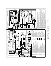
properly maintained. Refer to Fig. 24 for field wiring information
and to Fig. 39 for furnace wiring information.
NOTE: If the polarity is not correct, the STATUS LED on the
control will flash rapidly and prevent the furnace from heating.
The control system also requires an earth ground for proper
operation of the control and flame-sensing electrode.
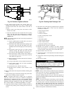
The 24-v circuit contains an automotive-type, 3-amp fuse located
on the control. (See Fig. 23.) Any shorts of the 24-v wiring during
installation, service, or maintenance will cause this fuse to blow. If
fuse replacement is required, use ONLY a 3-amp fuse. The control
LED will display status code 24 when fuse needs to be replaced.
Proper instrumentation is required to service electrical controls.
The control in this furnace is equipped with a Status Code LED
(Light-Emitting Diode) to aid in installation, servicing, and
troubleshooting. It can be viewed through the sight glass in blower
access door. The furnace control LED is either ON continuously,
rapid flashing, or a code composed of 2 digits. The first digit is the
number of short flashes, the second digit is the number of long
flashes.
For an explanation of status codes, refer to service label located on
blower access door or Fig. 43, and the troubleshooting guide at the
end of this procedure. The furnace control will store 1 status code
for 72 hours.
For Controls With a Red LED
The stored status codes WILL be erased from the control memory,
if 115- or 24-v power is interrupted.
1. To retrieve status code, proceed with the following:
NOTE: NO thermostat signal may be present at control, and all
blower-OFF delays must be completed.
a. Leave 115-v power to furnace turned on.
b. Remove outer access door.
c. Look into blower access door sight glass for current LED
status. DO NOT remove blower access door or terminate
115-v power to control or status code will be lost.
d. BRIEFLY remove insulated terminal wire from the draft
safeguard switch (DSS) until LED goes out (1 to 2 sec),
then reconnect it.
2. When above items have been completed, the LED flashes
status code 4 times. Record this status code for further
troubleshooting.
3. Component self-test will begin. Refer to COMPONENT
TEST section for complete test sequence.
4. Check LED status.
5. Refer to the SERVICE label on the front of the blower access
door for more information.
Component Self-Test
Component Test can also be initiated by performing the following:
1. Remove outer access door.
2. Remove blower access door.
3. Remove the wire from the ″R″ terminal of the control board.
4. Manually close blower access door switch.
Blower access door switch opens 115-v power to control. No
component operation can occur unless switch is closed.
Caution must be taken when manually closing this switch for
service purposes. Failure to follow this warning could result
in electrical shock, personal injury, or death.
5. BRIEFLY short (jumper) TEST/TWIN, 3/16-in. quick-
connect male terminal on control (behind Y terminal) to the
C
OM-24V terminal on furnace control. (See Fig. 23.)
30
→