


Furnace control must be grounded for proper operation or
control will lock out. Control is grounded through
green/yellow wire routed to gas valve and manifold bracket
screw.
115-V WIRING
Verify that the voltage, frequency, and phase correspond to that
specified on unit rating plate. Also, check to be sure that service
provided by utility is sufficient to handle load imposed by this
equipment. Refer to rating plate or Table 5 for equipment electrical
specifications. Make all electrical connections in accordance with
National Electrical Code (NEC) ANSI/NFPA 70-2002 and any
local codes or ordinances that might apply. For Canadian instal-
lations, all electrical connections must be made in accordance with
Canadian Electrical Code CSA C22.1 or authorities having juris-
diction.
Do not connect aluminum wire between disconnect switch
and furnace. Use only copper wire.
Use a separate, fused branch electrical circuit with a properly sized
fuse or circuit breaker for this furnace. See Table 5 for wire size
and fuse specifications. A readily accessible means of electrical
disconnect must be located within sight of the furnace.
NOTE: Proper polarity must be maintained for 115-v wiring. If
polarity is incorrect, control LED status indicator light will flash
rapidly and furnace will NOT operate.
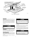
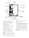
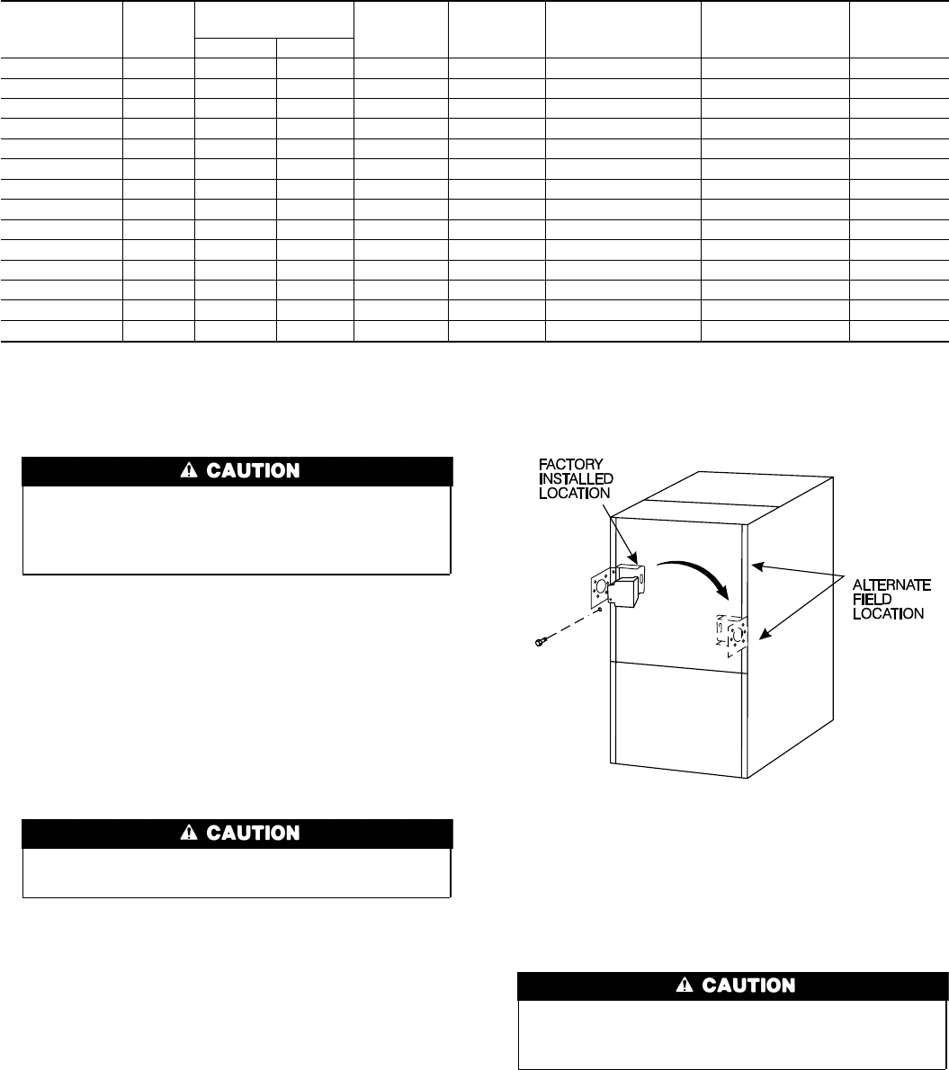
J-BOX RELOCATION
NOTE: If factory location of J-Box is acceptable, go to next
section (J-Box Cover Installation).
NOTE: On 14″ wide casing models, the J-Box shall not be
relocated to other side of furnace casing when the vent pipe is
routed within the casing.
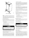
1. Remove screws holding auxiliary J-box. (See Fig. 22.)
2. Cut wire tie on loop in wires to J-box.
3. Locate box to desired location.
4. Fasten J-Box to casing with screws.
5. Route J-box wires within furnace away from sharp edges and
hot surfaces.
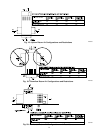
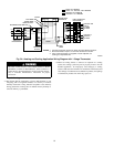
ELECTRICAL CONNECTION TO J-BOX
If manual disconnect switch is to be mounted on furnace,
select a location where a drill or fastener will not contact
electrical or gas components.
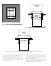
1. Attach electrical box to J-Box bracket.
2. Route wires through hole in electrical box and J-Box bracket.
3. Secure ground wire to green screw on J-Box bracket.
4. Connect line voltage leads as shown in Fig. 24.
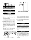
FOR POWER CORD INSTALLATION
Power cords must be able to handle the electrical requirements
listed in Table 5. Refer to power cord manufacturer’s listings.
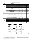
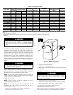
→ Table 5—Electrical Data
UNIT SIZE
VOLTS-
HERTZ-
PHASE
OPERATING
VOLTAGE RANGE
MAXIMUM
UNIT AMPS
UNIT
AMPACITY#
MAXIMUM
WIRE LENGTH (FT)‡
MAXIMUM
FUSE OR CKT BKR
AMPS†
MINIMUM
WIRE GAGE
Maximum* Minimum*
045-08/024045 115-60-1 127 104 5.6 7.77 47 15 14
045-12/036045 115-60-1 127 104 7.0 9.47 39 15 14
070-08/024070 115-60-1 127 104 5.0 7.06 52 15 14
070-12/036070 115-60-1 127 104 6.7 9.19 40 15 14
070-16/048070** 115-60-1 127 104 9.8 12.59 28 15 14
090-14/042090 115-60-1 127 104 8.1 10.83 34 15 14
090-16/048090 115-60-1 127 104 9.8 12.95 28 15 14
090-20/060090** 115-60-1 127 104 12.9 17.60 34 20 12
110-12/036110 115-60-1 127 104 8.2 10.75 34 15 14
110-16/048110 115-60-1 127 104 10.1 13.12 28 15 14
110-22/066110 115-60-1 127 104 13.7 17.62 32 20 12
135-16/048135 115-60-1 127 104 10.1 13.12 28 15 14
135-22/066135 115-60-1 127 104 14.4 18.55 30 20 12
155-22/060155 115-60-1 127 104 15.0 19.33 29 20 12
* Permissible limits of the voltage range at which the unit operates satisfactorily.
# Unit ampacity = 125 percent of largest operating component’s full load amps plus 100 percent of all other potential operating components’ (EAC, humidifier, etc.) full load
amps.
† Time-delay type is recommended.
‡ Length shown is as measured 1 way along wire path between unit and service panel for maximum 2 percent voltage drop.
** Preliminary
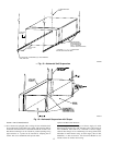
Fig. 22—Relocating J-Box
A02099
TWO
16