


f. Check and verify burner orifice size in furnace. NEVER
ASSUME ORIFICE SIZE. ALWAYS CHECK AND
VERIFY.
g. Replace orifice with correct size if required by Table 13 or
14. Use only factory-supplied orifices. See EXAMPLE 2.
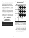
22,000 BTUH burner applications use Table 10
EXAMPLE 2: (0–2000 ft altitude)
Heating value = 1000 Btu/cu ft
Specific gravity = 0.62
Therefore: Orifice No. 43*
Manifold pressure: 3.7-in. wc
* Furnace is shipped with No. 43 orifices. In this example
all main burner orifices are the correct size and do not need
to be changed to obtain proper input rate.
3. Adjust manifold pressure to obtain correct input rate.
a. Turn gas valve ON/OFF switch to OFF
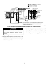
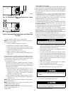
b. Remove manifold pressure tap plug from gas valve. (See
Fig. 40.)
c. Connect a water column manometer or similar device to
manifold pressure tap.
d. Turn gas valve ON/OFF switch to ON.
e. Set thermostat to call for heat.
f. Jumper R and W thermostat connections on furnace control
board to start furnace.
g. Remove regulator seal cap and turn regulator adjusting
screw counterclockwise (out) to decrease input rate of
clockwise (in) to increase input rate.
h. Install regulator seal cap.
i. Leave manometer or similar device connected and proceed
to Step 4.
NOTE: DO NOT set manifold pressure less than 3.2-in wc or
more than 3.8-in. wc for natural gas at sea level. If manifold
pressure is outside this range, change main burner orifices or refer
Table 10 or 11.
NOTE: If orifice hole appears damaged or it is suspected to have
been redrilled, check orifice hole with a numbered drill bit of
correct size. Never redrill an orifice. A burr-free and squarely
aligned orifice hole is essential for proper flame characteristics.
SEE NOTES: 1,2,4,7,8,9
A02064
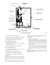
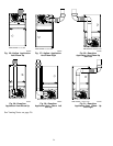
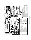
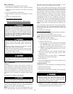
Fig. 32—Horizontal Left Application-Vent Elbow Left
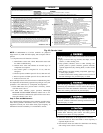
Fig. 33—Horizontal Left Application-Vent Elbow Right
then Up
A02065
SEE NOTES: 1,2,4,5,7,8,9
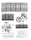
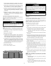
SEE NOTES: 1,2,4,5,7,8,9
A02066
Fig. 34—Horizontal Left Application-Vent Elbow Up
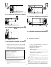
SEE NOTES: 1,2,4,5,7,8,9
A02067
Fig. 35—Horizontal Left Application-Vent Elbow Right
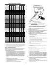
A02068
Fig. 36—Horizontal Right Application-Vent Elbow Left
SEE NOTES: 1,2,4,5,7,8,9
See Venting Notes on Page 26
25