


11. ELECTRICAL MECHANISM
Z-8550A, 8560A
90
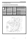
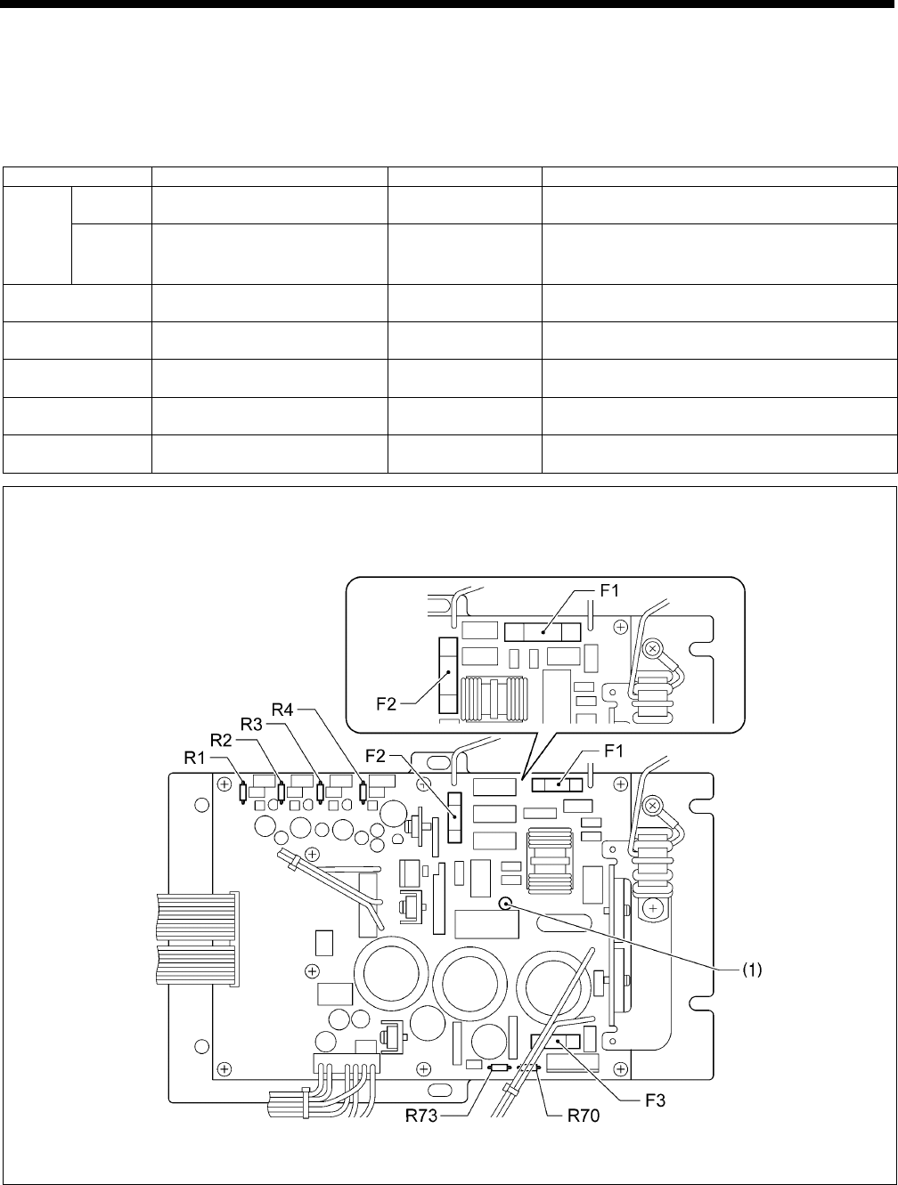
11-3. Description of fuses
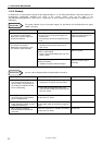
11-3-1. Power supply P.C. board (fuses and fuse resistors)
When replacing the fuses and fuse resistors, be sure to use the parts specified below.
If the components on the P.C. boards are damaged, the fuses may blow again soon even after they have been replaced.
No. Part name Parts code Symptom when fuse blows
200 V
system
Fuse 10A
(Glass tube fuse 10A-250V)
J 04417-001
Power does not turn on and red LED (1) on
power supply P.C. board does not illuminate.
F1,
F2
100 V
system
Fuse 20A
(Glass tube fuse 20A-250V)
J 02585-001
Power does not turn on and red LED (1) on
power supply P.C. board does not illuminate.
F3
Fuse 5A
(Glass tube fuse 5A-250V)
J 04418-001
Needle zigzag motor does not operate and
[Err 200] is displayed.
R70 Fuse resistor 1/2W 0.47Ω J 04415-001
Needle zigzag motor does not operate and
[Err 200] is displayed.
R73 Fuse resistor 1/2W 0.22Ω J 02754-001
Needle zigzag motor does not operate and
[Err 200] is displayed.
R1, R2, R3 Fuse resistor 1/4W 0.47Ω J 04482-001
Sewing machine motor does not operate and
[Err 130] is displayed.
R4 Fuse resistor 1/2W 0.47Ω J 04415-001
Sewing machine motor does not operate and
[Err 130] is displayed.
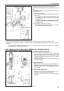
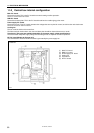
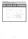
* The diagram of the power supply P.C. board shown below is for the 200 V systems. The power supply P.C. board for
100 V systems are the same as the one for 200 V systems except for the section indicated in the diagram.
0161B
100V