


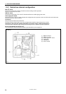
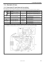
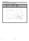
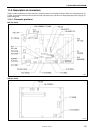
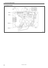
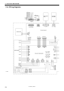
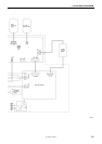
11. ELECTRICAL MECHANISM
Z-8550A, 8560A
97
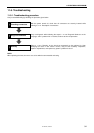
11-5-3. Remedy
If a problem No. is reached while carrying out the diagnosis steps in “11-5-2. Diagnosis flowchart”, refer to the table for the
corresponding number.After identifying the cause in the “Cause” column, carry out the steps in the
“Inspection/Remedy/Adjustment” column, and if a malfunction is found, replace the parts specified in “Replacement if a
malfunction”.
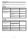
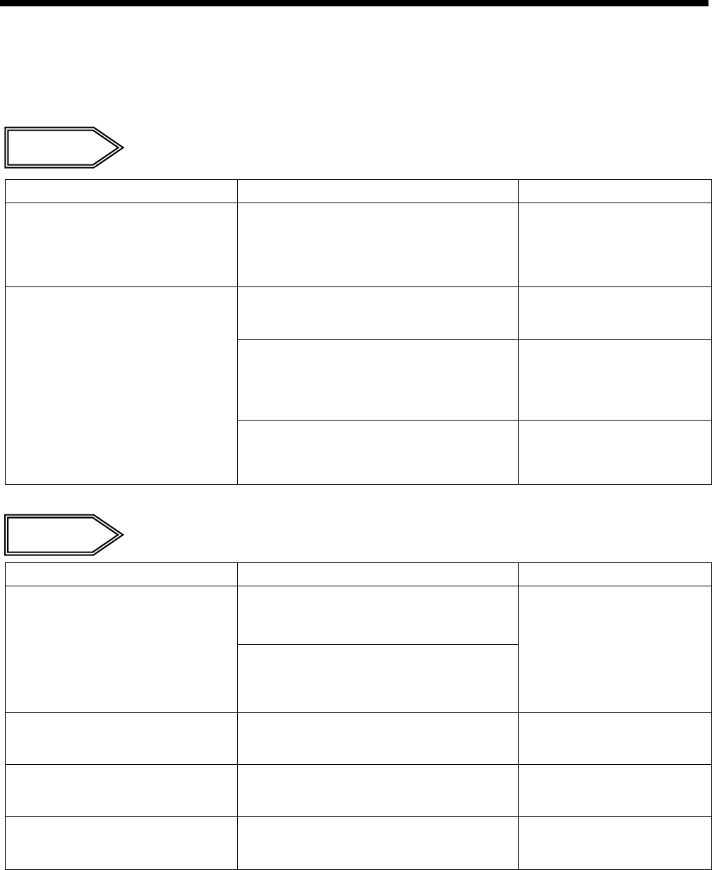
Problem No. 1
The power indicator (red) on the power supply P.C. board does not illuminate when the power
switch is turned on.
Cause Inspection/Remedy/Adjustment Replacement if a malfunction
1. If the red LED on the power supply
P.C. board is not illuminated:
Malfunction of power supply P.C.
board or transformer
Check the power cord.
• Is fuse F1 or F2 on the power supply P.C.
board blown?
• Is the primary coil of the transformer burnt
out?
If fuse F1 or F2 is blown,
replace the power supply P.C.
board or transformer.
1) Check if the secondary coil of the
transformer is burnt out or if there is an
open circuit.
Transformer
If the power indicator (green) on the main P.C.
board is not illuminated:
2) Check if fuse resistor R25 on the main P.C.
board is blown.
Main P.C. board
2. If the red LED on the power supply
P.C. board is illuminated:
Malfunction of transformer, main
P.C. board or panel assembly
If the power indicator (green) on the main P.C.
board is illuminated:
3) (Replace the part(s) indicated at right.)
Main P.C. board or panel
assembly
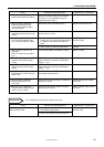
Problem No. 2
An error code is displayed when the power switch is turned on.
Cause Inspection/Remedy/Adjustment Replacement if a malfunction
1) Check if thread scraps are blocking the
cooling fans (for oil pan and control box).
1. When [Err 740] is displayed:
The cooling fan for the oil pan is
disconnected or not operating, or
the cooling fan inside the control
box is not operating. 2) Check that connector P23 (FAN1) and
connector P32 (FAN2) are inserted into the
main P.C. board.
DC fan motor assembly
2. When [Err 65] is displayed:
One of the keys on the operation
panel is still depressed.
Check that connector P21 (PANEL) is inserted
into the main P.C. board.
Panel assembly
3. When [Err 95] is displayed:
Power switch was turned on while
treadle was depressed.
Return the treadle to the neutral position and
turn the power switch off and back on again to
check.
Treadle unit
4. When [Err 90] is displayed:
Poor connection for treadle unit
connector
Check that connector P11 (PEDAL) is inserted
into the main P.C. board.
Treadle unit