


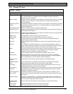

ICP-CC404 | Installation Guide | 20.0 Terminals and Descriptions
Bosch Security Systems, Inc. | 12/08 | F01U089401-02 83
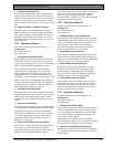
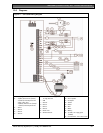
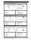
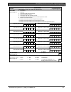
Figure 13: Telecom Connection Diagram for Australia
1
2
3
9
7
4
5
6
10
2
3
9
7
8
1 – Control panel
2 – Red wire
3 – Yellow wire
4 – 6P4C plug (top view)
5 – 605 plug
6 – Internal phones
7 – Green wire
8 – Telecom line
9 – Black wire
10 – 611 socket
1 (green): internal phone line
2 (black): telecom line (street)
3 and 4: not connected
5 (yellow): internal phone line
6 (red): telecom line (street)
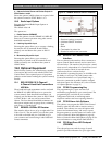
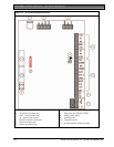
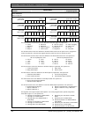
Figure 14: Telecom Connection Diagram for New Zealand
1
3
2
4
5
6
7
8
9
1 – Control panel
2 – Black wire
3 – Red wire
4 – RJ45 plug (top view)
5 – Internal phones
6 – Telecom line
7 – (black): telecom line (street)
(green): internal phone line
(red): telecom line (street)
(yellow): internal phone line
8 – Green wire
9 – Yellow wire
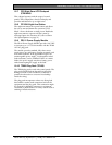
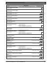
Figure 15: Telecom Connection Diagram for China
1 2 3 4 5
6
7
8
10 9
1 – Control panel
2 – Red wire
3 – Black wire
4 – 4P4C plug (top view)
5 – RJ12 plug (top view)
6 – Telecom line
7 – Internal phones
8 – Rear view of telephone plate
(green): internal phone line
(black): telecom line (street)
(yellow): internal phone line
(red): telecom line (street)
9 – Yellow wire
10 – Green wire