


ICP-CC404 | Installation Guide | 20.0 Terminals and Descriptions
Bosch Security Systems, Inc. | 12/08 | F01U089401-02 81
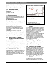
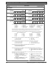
20.3 Diagrams
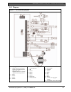
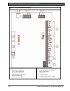
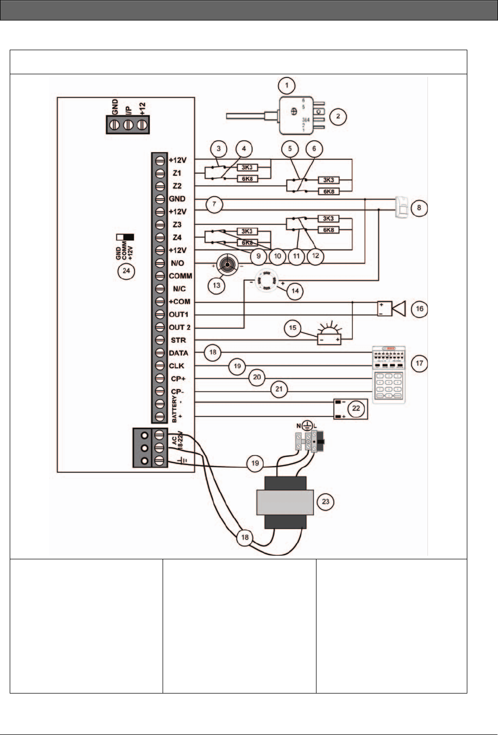
Figure 11: ICP-CC404 Wiring Diagram
1 – 605 plug
2 – 6 (Red) Telecom line (street)
5 (Yellow) Internal phone line
3 and 4 Not used
2 (Black) Telecom line (street)
1 (Green) Internal phone line
3 – Zone 1
4 – Zone 5
5 – Zone 2
6 – Zone 6
7 – Power to external equipment:
12 V @ 400 mA
8 – PIR
9 – Zone 8
10 – Zone 4
11 – Zone 7
12 – Zone 3
13 – Piezo siren
14 – Smoke detector
15 – Strobe
16 – Horn speaker
17 – Codepad
18 – Yellow
19 – Green
20 – Red
21 – Black
22 – Battery
23 – 18 VAC 1.3 A plug pack
(TF008)
24 – Link between +12 V and Comm