


ICP-CC404 | Installation Guide | 19.0 Optional Equipment
76 Bosch Security Systems, Inc. | 12/08 | F01U089401-02
4 – Alarms Activate Sirens and Strobe Outputs in
STAY Modes 1 and 2
Select this option if audible alarms are required when
the system is armed in STAY Mode 1 or 2.
18.8 Radio Input Options
Program the selected Radio Input Options in
Location 431.
The default value is 0.
The options are:
1 – Radio Receiver (WE800E)
Select this option to use the WE800E 433 MHz RF
Receiver for remote operations using radio remote
hand-held transmitters.
2 – Latching Keyswitch Input
Selecting this option allows you to connect a latching
keyswitch to the P5 terminals D and GND to
remotely arm and disarm the system in AWAY
Mode.
3 – Momentary Keyswitch Input
Selecting this option allows you to connect a
momentary keyswitch to the P5 terminals D and
GND to remotely arm and disarm the system in
AWAY Mode.
19.0 Optional Equipment
Bosch Security Systems, Inc. manufactures a number
of accessories that can be used with the ICP-CC404
Control Panel. These optional pieces of equipment
enhance certain features making the system extremely
flexible.
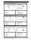
19.1 RE012E/RE013E 2-Channel/
4-Channel Hand-Held Transmitters
433 MHz
These hand-held radio transmitters can be used with
the RE005E 433 MHz RF Receiver to operate the
system remotely. Both hand-held transmitters can
remotely arm and disarm the system in AWAY Mode
or STAY Mode 1 and can activate remote Panic
Alarms. The four-channel hand-held transmitter can
also operate outputs such as garage doors, swimming
pool pumps, or outside lights.
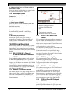
19.2 WE800E 433 MHz RF Receiver
This interface allows the use of up to eight radio User
Codes (9 to 16). This is useful if you want the system
to be radio controlled and you would like to give
your customer total control using a radio hand-held
remote transmitter.
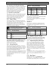
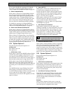
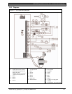
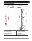
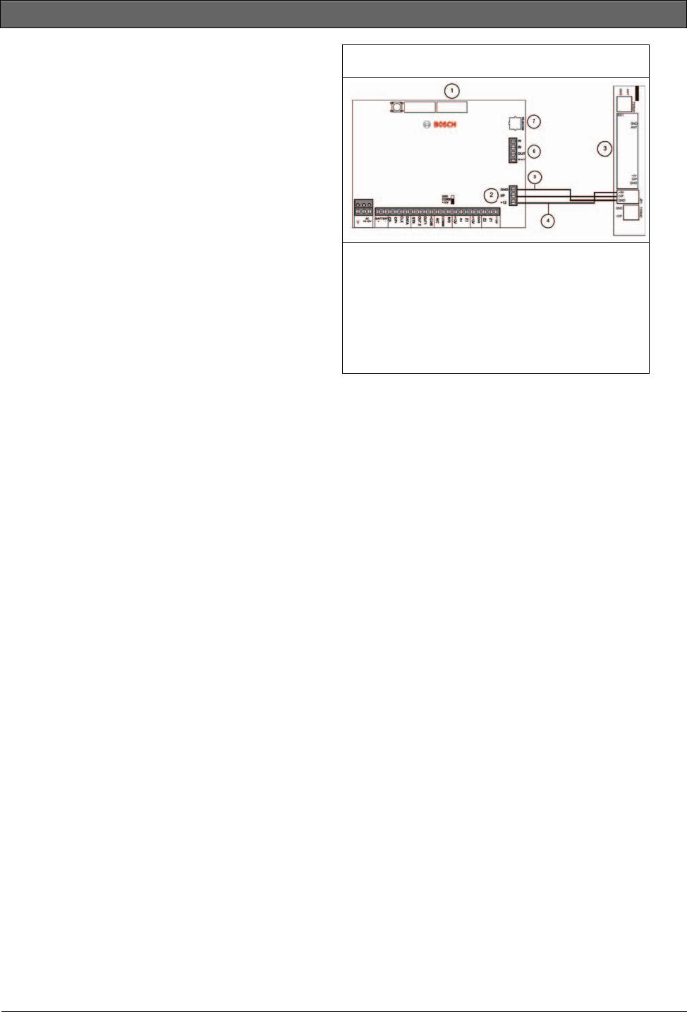
Figure 10: WE800E Wireless ON/OFF Interface
1 – Direct link cable
2 – Receiver interface connection
3 – Wireless ON/OFF Interface
4 – Red
5 – Black
6 – Termination for phone line
7 – Socket for telecom lead connection
19.3 RE005E Two-Channel Radio
Interface
The two-channel radio interface allows customers to
operate Control Panels remotely and to control two
on-board relays. The interface can be used as a stand-
alone receiver, independent of a Control Panel, used
solely for remote control of external devices
connected to the two on-board relays.
The interface’s operating frequency is 433 MHz with
the ability to store up to 120 radio remote codes.
Connect the interface to a Control Panel using a
three-wire connection in parallel with the codepad
and select Option 8 in Location 427 (refer to Section
18.4 System Options 4 on page 74).
19.4 CC891 Programming Key
The programming key copies and stores all
information programmed in your control panel. The
programming key can hold all your common
configuration data such as monitoring station
telephone numbers and zone reporting channels.
19.5 CC816 Alarm Link Software
This software can program the ICP-CC404 Control
Panel by either the direct link or remote connect
methods. This software can access all options and
features and maintain history and service reports.
Program options to use this feature in Location 180
(refer to Section 8.2 Alarm Link Options on page 40).
Refer to Section 8.0 Alarm Link Software on page 39 for
more information on using Alarm Link Software.
19.6 CP5 Eight Zone LED Codepad
(CP508W)
This codepad operates with the range of control
panels. It provides indications for up to eight zones.