


ICP-CC404 | Installation Guide | 11.0 Dialer Information
46 Bosch Security Systems, Inc. | 12/08 | F01U089401-02
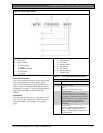
System Status
The system status information is shown by four digits,
which are defined in Figure 6 on page 45. The first
digit indicates whether the system is armed or
disarmed. The second digit indicates whether a
codepad alarm was activated by the operator (refer to
Section 4.7 Codepad Duress Alarm on page 21 through
Section 4.10 Codepad Medical Alarm on page 21 for
more information). The third digit indicates the status
of the AC MAINS supply. The fourth digit indicates
whether a system fault occurred at the control panel
(refer Section 4.12 Fault Analysis Mode on page 22 for
more information.
11.0 Dialer Information
This section outlines the programming information
required for the ICP-CC404 Control Panel when
communicating with a base station receiver. These
parameters specify the telephone numbers to call, the
transmission formats, handshake tones, and
transmission speeds.
The control panel can report event information from
two on-board dialers. The first dialer reports to
Receiver 1 and the second dialer reports to Receiver
2. You can program each dialer with two separate
telephone numbers, handshake tone, reporting format
type, and Subscriber ID Number.
Example
You can set up Dialer 1 to report in Domestic Dialing
Format to Receiver 1 and set up Dialer 2 to report to
a base station receiver in Contact ID Format only if
Dialer 1 is unsuccessful.
To program a telephone number:
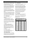
You must program a 0 as 10. Each location in the
primary, secondary, and callback telephone numbers
stores one digit of the telephone number.
You must insert a 0 at the end of a telephone number
to indicate to the dialer the end of the telephone
number is reached. The dialing sequence ends when
a 0 appears. Refer to Table 38.
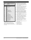
Table 38: Dialing Digits
Digit
Required
Number to
Program
Digit
Required
Number to
Program
terminator 0 8 8
1 1 9 9
2 2 0 10
3 3 * 11
4 4 # 12
5 5 4 sec pause 13
6 6 break 14
7 7
Example
To program the telephone number 9672 1055 as the
Primary Telephone Number for Receiver 1, program
the following sequence into Locations 000 to 015:
[9 6 7 2 1 10 5 5 0 0 0 0 0 0 0 0]
To enter a 4-sec pause in the dialing sequence,
program a 13. A pause might be necessary when the
dialer communicates through an old (slower)
telephone exchange or when a PABX system is in
place.
Example
To program the number 02 pause 9 672 1055, enter:
[10 2 13 9 6 7 2 1 10 5 5 0 0 0 0 0].
Table 38 shows how to program the numbers, keys,
and functions for a telephone number.
11.1 Primary Telephone Number for
Receiver 1 and Receiver 2
Program the Primary Telephone Number for
Receiver 1 in Locations 000 to 015.
Program the Primary Telephone Number for
Receiver 2 in Locations 040 to 055.
The default value for both telephone numbers is
0 0 0 0 0 0 0 0 0 0 0 0 0 0 0 0.
When the control panel sends a report, Number this
number to contact the monitoring station or pager,
for example. If the call is successful, the information
is sent and the dialer returns to Standby Mode.
If unsuccessful, the dialer attempts two more calls
using the Primary Telephone Number for Receiver 1.
If these calls are unsuccessful, the dialer calls the
Secondary Telephone Number for Receiver 1 up to
three times. If the dialing sequence is still
unsuccessful, the control panel repeats this sequence
by dialing the Primary and Secondary Telephone
Numbers for Receiver 2 (if they are programmed).
If the first six attempts are unsuccessful and no
telephone numbers for Receiver 2 are programmed,
this procedure is repeated only once, for up to twelve
call attempts per alarm, after ten min.
If the Primary and Secondary Telephone Numbers
for Receiver 2 are also programmed, the control
panel attempts up to 24 calls per alarm.
Contact your monitoring station or pager company
for the correct telephone numbers before you
program these locations.