


ICP-CC404 | Installation Guide | 14.0 Zone Information
Bosch Security Systems, Inc. | 12/08 | F01U089401-02 53
14.0 Zone Information
14.1 Day Alarm Information
Program the desired Day Alarm Zones in
Location 265.
The default value is 0.
The options are:
1 – Zone 1
2 – Zone 2
3 – Zone 3
4 – Zone 4
You can select any combination of the options by
programming a single value. Calculate this value by
adding the option bit numbers together. Refer to
Section 2.3 Programming Option Bits on page 10 for
more information.
Day Alarm allows some zones to be monitored when
the system is disarmed. Visual or audible indications
are available at any of the programmable outputs,
including the codepad buzzer. This function
accommodates latching and non-latching Day Alarm
Output Event Types.
When the system is armed in AWAY Mode, STAY
Mode 1, or STAY Mode 2, zones programmed as
Day Alarm Zones activate the sirens and dialer just as
non-Day Alarm Zones do. When Day Alarm is
activated, it ignores any zone Pulse Count settings
programmed for that zone (that is, the zone Pulse
Count is only relevant when the system is armed).
Example
You can set up a Day Alarm at the front door of a
shop with a pressure mat or electronic beam that is
activated when a customer enters the shop. When a
customer walks on the pressure mat or breaks the
electronic beam, the codepad buzzer beeps.
14.1.1 Day Alarm Resetting
An output programmed for Day Alarm Resetting
operates when a zone programmed for Day Alarm is
activated. The output is reset after the zone is
resealed. This occurs only when the system is
disarmed. Refer to Output Event Type 0,14 Day Alarm
Resetting on page 66 for more information.
14.1.2 Day Alarm Latching
An output programmed for Day Alarm Latching
operates when a zone programmed for Day Alarm is
activated. The zone indicator and the latching output
is reset when [AWAY] is pressed. This occurs only
when the system is disarmed. Refer to Output Event
Type 0,15 Day Alarm Latching on page 66 for more
information.
14.1.3 Day Alarm Operation
If a zone is programmed for Day Alarm, the zone can
be isolated in the normal way so that it does not
register as a Day Alarm Zone when the system is
disarmed. You can only use Zones 1 to 4 as Day
Alarm Zones.
You can program the STAY indicator to indicate
whether Day Alarm is turned on or off by selecting
Option 8 in Location 428 (refer to Section 18.5
Consumer Options 1 on page 75). When Day Alarm is
on, the STAY indicator flashes once every three sec.
Zones 5 to 8 can be monitored by programming an
output to mimic a zone. Refer to Section 16.2 Output
Event Types on page 65 for more information on the
Output Event Types that you can program.
To turn Day Alarm on:
Press and hold [4] until three beeps sound.
To turn Day Alarm off:
Press and hold [4] until two beeps sound.
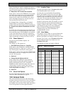
14.2 EOL Resistor Value
Program the EOL Resistor Value in Location 266.
The default value is 15.
Table 42: EOL Resistor Options
Option Resistor Value
0 No EOL
1
1 kΩ (brown, black, red)
2
1.5 kΩ (brown, green, red)
3
2.2 kΩ (red, red, red)
4
3.3 kΩ (orange, orange, black, brown) 1%
5
3.9 kΩ (orange, white, red)
6
4.7 kΩ (yellow, violet, red)
7
5.6 kΩ (green, blue, red)
8
6.8 kΩ (blue, grey, black, brown) 1%
9
10 kΩ (brown, black, orange)
10
12 kΩ (brown, red, orange)
11
22 kΩ (red, red, orange)
12 Reserved
13 Reserved
14 Reserved
15 Split EOL 1% resistors
You can program the control panel for different EOL
(end-of-line) resistor values (refer to Table 42). This is
a global parameter that affects all zones
simultaneously. This feature allows you to install the
ICP-CC404 Control Panel at an existing site without
changing the EOL resistors. This feature also
increases the security of the system because eleven
possible EOL resistor values can be used, which
makes it extremely difficult to tamper with the
system.