


Instruction 2772-0803 Page S-A1
REMOTE INTELLIGENT SENSOR - AREA MONITOR
Several references to RlS’s manufactured before April 1992 with phase 1 base
boards have been given in the main manual (Sections 1.1, 1.3.7, 2.8.2.1, & 4.4) Any
references to Figure 2-3 should be refered to Figure S-3.
The light level adjustment POTs for boards manufactured before April 1992 are
mounted under the tape cassette which has to be removed before the light levels can be
adjusted as explained below:
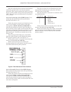
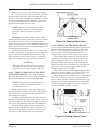
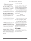
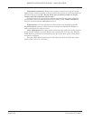
Enter the TEST Mode by pressing the red button on the back of the door. Wait until
the display has cycled to show:
200 to 254
1
200 to 254
1
HOLD
Figure S-1. Test Mode
This display status will be maintained for 5 minutes, or until the HOLD/RELEASE
button is pressed again.
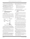
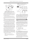
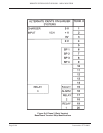
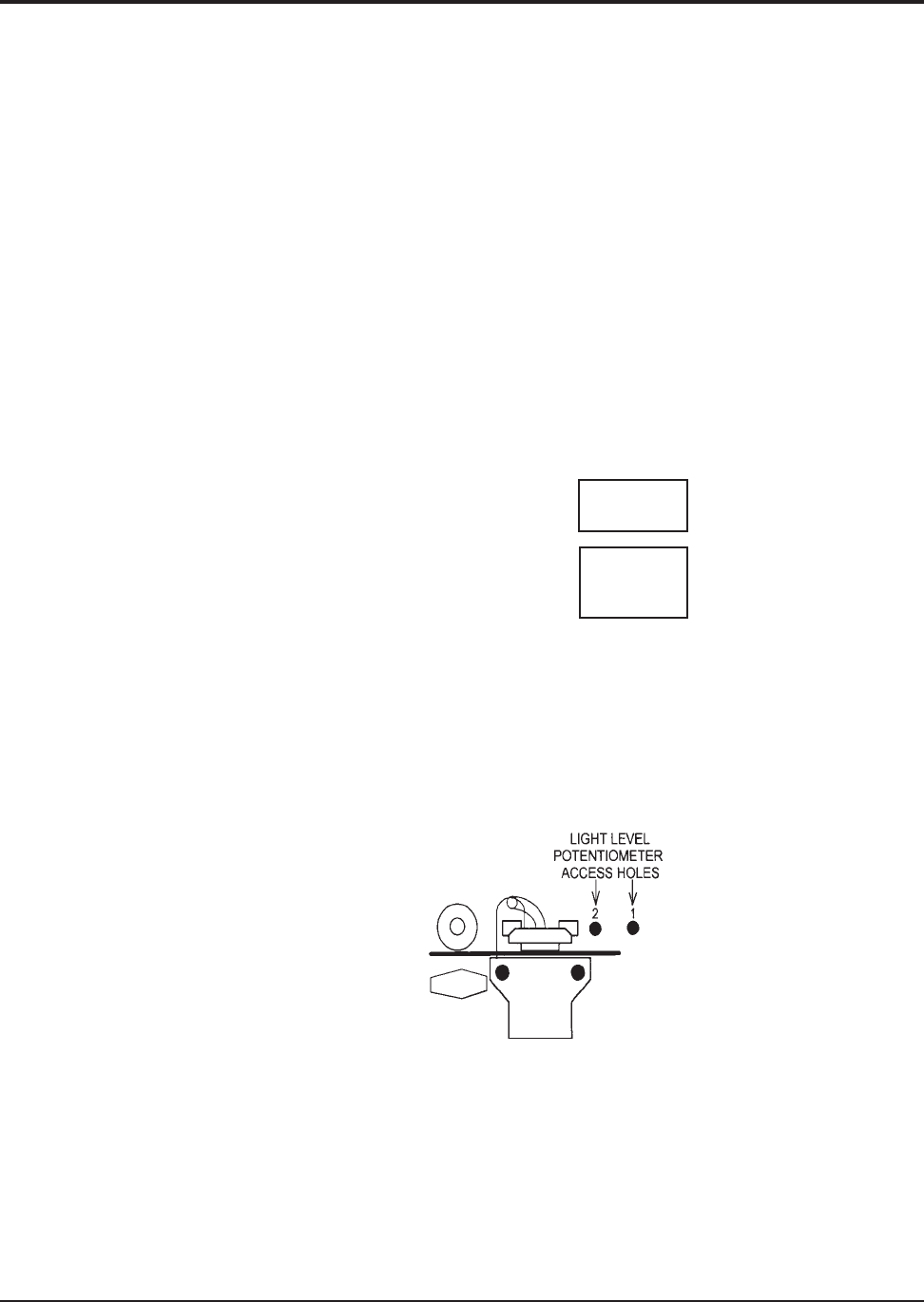
Adjustment is made by means of the two potentiometers that are located under the
cassette position and accessed through holes in the top plate. The light level track 1 is
adjusted by one, and track 2 by the other. The potentiometer access holes cannot be
seen until the cassette is removed. See Figure S-2.
Figure S-2. Pre-4/92 Light Level Access Holes
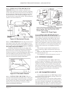
Adjustment method ‘a’. Make sure that tape in the gate is clean and unstained.
Close the tape gate. Observe the displayed light level for track 1 and decide if it needs
increasing or decreasing.
Open the tape gate and remove the cassette, turn the appropriate potentiometer a
little clockwise to decrease, or counter clockwise to increase, the light level.
Reinstall the cassette and check the light level value; if necessary repeat this
process until a value of 220 is achieved.
A1.1 ADJUSTING LIGHT LEVELS ON PHASE 1 RIS UNITS
SUPPLEMENT A
A1 EARLIER RIS BASE BOARDS
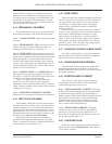
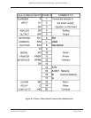
Press the HOLD/RELEASE button
on the front panel firmly so that
the display shows: