


REMOTE INTELLIGENT SENSOR - AREA MONITOR
Instruction 2772-0803 Page 4-7
entered. These practices, if regularly carried out,
will build up an informative system history. This
will show trends and prove a useful diagnostic aid
should this be required. The time taken to check
and record parameters for each cassette change is
normally only a few minutes.
4.14 MECHANICAL TIGHTNESS
It is good practice to carry out an annual check
of mechanical security. The check should include:
4.14.1 CABLE GLANDS. Check that cable glands
are tight.
4.14.2 DOOR SWITCH. Make sure that the door
switch is correctly adjusted. The procedure for
checking and adjustment is in Section 4.7.
4.14.3 DOOR SEALS. Ensure the door seals are
effective. Also check that the door securing screws
are in sound condition and not strained to the point
that replacement is required. The door seals are
reliable and seldom need attention. Door securing
screws can be strained by over tightening and it is
recommended that spares are carried. The catalog
number is shown in Section 5.
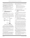
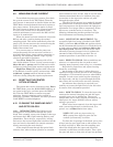
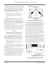
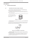
4.14.4 SAMPLE INLET. It is ESSENTIAL that
the input tubes is properly engaged in the block.
Otherwise a suitable, undiluted, sample will not be
conveyed to the point of measurement.
There is no reason for the tube to become
displaced on its own, however the functional
importance of this element fully justifies a careful
check. Correct assembly of the input tubes is shown
in Figures 2-4 and 2-5.
4.14.5 INTERFACE TERMINAL SCREWS.
Check the screw in each used terminals for tightness.
4.15 INPUT PATH CLEANING
Occasionally, check for excessive paper dust in
the open tape gate. A check every 2 or 3 months is
usually adequate. If it is required, blow the tape
path and block clean with a hand bellows or can of
pressurized air. The use of a factory air line is not
recommended unless the air supply is known to be
filtered and dry and it is used carefully.
More extensive cleaning is not normally re-
quired unless sampling conditions are very dirty,
dusty, or otherwise adverse. If additional cleaning
proves necessary, see Section 4.10.
4.16 PUMP CHECK
Annually check the sampling pump for excessive
current and noise (see Section 4.8). These checks do
not require physical pump access but any further
examination, or pump replacement, will require
removal of the mechanical chassis in which the
pump is mounted.
Indicators of excess current and noise, referred
to above, may result from wear in motor bearings, or
the eccentric. Misalignment or looseness of the
motor relative to pump body is another possible
cause. If wear is the problem, replace the complete
motor/pump assembly. Misalignment, if not accom-
panied by wear, can be adjusted. For pump replace-
ment catalog numbers see Section 5.
4.17 CHARCOAL FILTER & TUBING CHECK
Annually, or biannually, access the pneumatic
module (under the mechanical chassis), change the
filter and clean the tubing as necessary.
4.18 TROUBLESHOOTING GENERAL
The following sections assume the reader has
appropriate competence and skill. In case of any
doubt or difficulty refer to one of our Service Centers
for expert assistance.
4.19 EXCESSIVE INPUT CURRENT
Any increase in the input current should be
investigated and accounted for. The most likely
reasons for high input current are:
4.18.1 HIGH CHARGING CURRENT. This may
be due to normal recharging after an extended period
of power interruption and the system running on
battery support. If this is the case the charging current
will reduce to normal after a period of some hours.
Other reasons for an increase in charging current
include a badly adjusted input voltage (see Section
2.8.2.1), and a deteriorating battery.
4.18.2 HIGH PUMP CURRENT. The pump
running current can be checked as described in
Section 4.8. If it has increased significantly it is
generally an indication that the pump is worn and
needs replacing (Section 4.11).
4.20 LOW PUMP FLOW
If the flow, when checked at cassette change, is
found to have reduced significantly, check for the
cause. These could be: