


REMOTE INTELLIGENT SENSOR - AREA MONITOR
Instruction 2772-0803 Page 4-5
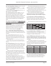
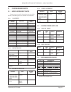
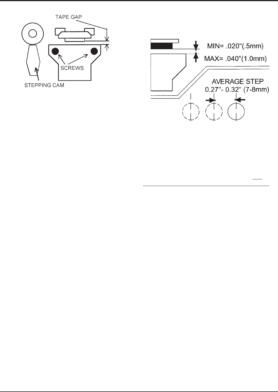
NOTE: If it is not possible to achieve a
satisfactory average tape step length, please
refer to additional information in
Section 4.21.2.
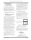
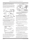
Figure 4-7. Summary of Gate & Step Values
4.10.7 WHAT TO DO IF CLEANING DOES NOT
RECTIFY THE PROBLEM. If performance cannot
be improved, or if the change is marginal, it will be
necessary to replace the optics block. A new optics
block can be ordered from your distributor. When
ordering the replacement block, specify the
RIS
system gas type and range, also the serial number.
This information will ensure that the correct item is
supplied.
It should be appreciated that if the block is
replaced the original calibration of the instrument is
no longer valid. It may be assumed that, because of
manufacturing methods and testing, performance
with a replacement block will be within 10% of the
original. Factory re-calibration against gas is recom-
mended as soon as is practicable.
A replacement block carried as a spare against
future need is a wise precaution for those applica-
tions where contamination of the input tube and
optics block is a problem.
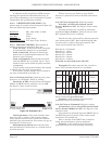
4.11 CHANGING A PUMP
Providing that care is taken, this is not a
difficult procedure.
4.11.1 PREPARATION. Have available a replace-
ment pump of the correct type. RIS systems with a
Flow Rate of 200 mL/min. or less are fitted with the
low flow pump and RIS’s with a Flow Rate higher
than 200 mL/min. are fitted with the high flow
pump. These catalog numbers specify the pump
complete with mounting bracket ready to fit.
Warn that the system is being taken out of
operation and that alarms may be activated during
the work. Remove external power from the RIS, open
the door and turn off SW1.
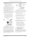
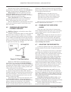
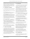
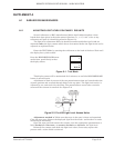
Figure 4-6. Stepping Clamp Vertical
With the stepping cam vertical, and gate
opening lever in the gate closed position, the optics
block can be replaced and the two screws put in
loosely. Position the optics block so that there is a
gap of 0.020" to 0.040" (0.5mm to 1.0mm) between
the two halves of the gate.
Ensure that the gap is parallel when it is
measured. Note that the plastic tubes connecting
the moving part can cause it to twist a little in its
pivot. This can make the gap closer at the top or the
bottom.
After initially setting the gap, tighten the block
fixing screws to lock the optics block in position.
Replace the connector (with the switch ‘off ’),
then, verify that the tape steps correctly as follows.
Place a length of tape in the gate. This can be
done by pulling a length out of a cassette which can
be placed on top of the unit, or held in one hand.
Avoid touching tape with bare fingers.
Switch ‘on’, and press the tape reset button to
step on the tape. Mark the edge of the block on the
tape with a pencil. Repeat the process until 4 or 5
steps are marked on the tape. Measure the length
of the tape steps and take an average. The average
step should be between 0.27" and 0.32", (7 to 8 mm).
If the steps are much longer, the cassette life
will be less than the quoted 30-day maximum. In
this case, the position of the optics block may be
adjusted by repeating the above process, but
reducing the gap gradually. Continue until a tape
step of approximately 0.32"(8 mm) is achieved. Do
not reduce the gap to less than 0.020" (0.5 mm) or
tape drag in the gate may occur. This condition may
be aggravated if the tape gets damp. Tape breakage
can occur under these conditions.
NOTE: In some cases it may not be
possible to reduce the tape gap below about
0.030" (0.75 mm), in this case leave it set
at that value.