


REMOTE INTELLIGENT SENSOR - AREA MONITOR
Page 4-4 Instruction 2772-0803
Repeat several times, also with the gate open.
If a can of pressurized air is available, carefully
position tube at the tape side of the gate and blow
again several times. Suitable cans of air are usually
available from photographic suppliers. A mechani-
cal pump or bellows can be used but it may not be
possible to blow from the tape side.
NOTE: Take care to ensure that any dirt,
not trapped by the tape in the open gate, is
removed. Clean both holes in twin hole
blocks.
Carefully clean holes in block using a small
amount of cotton wool twisted onto a sliver of wood.
A normal sized cotton ‘bud’ or swab may be too
large. If necessary, use a little residue free solvent
spray on cotton wool as well. Afterwards, make sure
that no debris has been left during cleaning process
by blowing through again.
At this stage check the light levels to see if the
cleaning has effected an adequate improvement. If
it has, carefully reassemble the input tubes and,
after replacing a serviceable cassette, recheck the
light levels and put the system back into service.
CAUTION
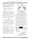
Make sure that the input tubes are properly
engaged in the block or the instrument will
not monitor accurately (Figures 2-4 & 2-5).
4.10.5 DIRECT CLEANING OF THE LED’S
AND PHOTO DIODES. If the limited cleaning
detailed above does not effect an adequate improve-
ment in the light levels perform the following.
NOTE: This procedure requires removal of
the optics block and should not be done
without good reason.
Remove the cassette. If the input tubes have
not already been removed, do so now. Take out the
two slot-head screws securing the optics block to
the mechanical chassis.
Carefully lift block without disconnecting the
leads or putting them under undue strain. It is now
possible to insert a small swab into the two holes in
the block. This should be done from the tape side.
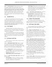
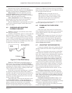
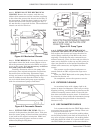
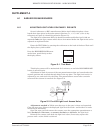
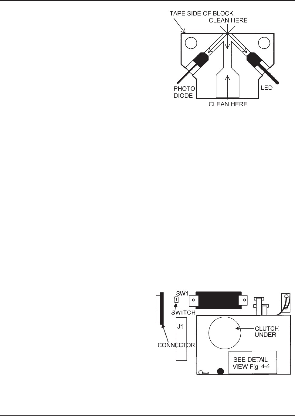
Gently find the angled cavities at the end of
which are mounted the optic devices (Figure 4-4),
clean both sides. Make sure that no lint or other
particles are left behind, blow out if necessary.
Figure 4-4. Cleaning Optics block
4.10.6 REPLACING THE OPTICS BLOCK.
Care is required when replacing the Optics block so
that it is correctly positioned relative to the other
half. It is first necessary to position the tape ad-
vance cam (on the left of the gate) so that it is
vertical. This can be achieved in one of two ways:
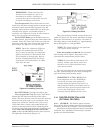
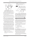
With switch SW1 turned off, find the take up
clutch on the mechanical chassis beneath the top
plate as shown in Figure 4-5. Turn the clutch by
moving the light colored gear at the bottom of the
clutch assembly (this is furthest away from the top
plate and it can be seen without taking the me-
chanical chassis out of the RIS).
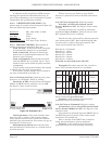
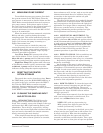
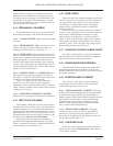
The clutch must be turned until stepping cam is
vertical as shown in Figure 4-6. The gear is a little
difficult to start turning because of the ratio.
The cam may also be positioned by turning switch
SW1 ‘off ’, remove the connector at the top left of the
unit as shown in Figure 4-5 and switch ‘on’ again, the
stepping cam will turn continuously. By turning SW1
‘off ’ at the appropriate point in the cam’s rotation, it
may be positioned vertically as shown.
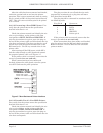
Figure 4-5. Finding Take Up Clutch