


REMOTE INTELLIGENT SENSOR - AREA MONITOR
Page 3-8 Instruction 2772-0803
The plug can then be cut off and the wire ends
prepared for termination in a plug that will mate
with that fitted on the RIS.
The plug should be connected in accordance with
the following table.
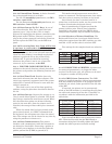
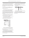
Plug Pin # Connect to:
1 to 3 No connection
4 DATA
5 BUSY
6 GROUND
7 Link to pin 6
If the printer cable is screened, ensure that the
screen is grounded at one end only.
When connections have been made and checked,
plug the printer into the RIS and check operation.
Refer to Section 3.16.3 for details of the available
printout modes.
After the cable has been connected and checked,
switch the system back on and test the printer
operation. This is most conveniently done by setting
the # 1 switch on SW1 of the printer option board to
‘OFF’. This will cause each data point to be printed
as it is stored.
3.14.5.2 Connecting a Non-GMD Printer. First
verify that the printer meets the specification
detailed in Section 3.14.2.
Check the printer manual and identify the wire
color, or pin number, on the printer cable that
corresponds to BUSY, DATA and GROUND. If
only the pin numbers are given, open the plug on
the end of the printer cable and write down the wire
color that corresponds. The plug can then be cut off
and the wire ends prepared for connection to the
RIS interface J1. Cut off any unused wires in the
printer cable.
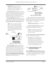
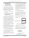
After turning off the RIS power switch SW1,
feed the cable through a cable gland and connect
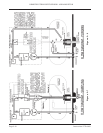
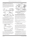
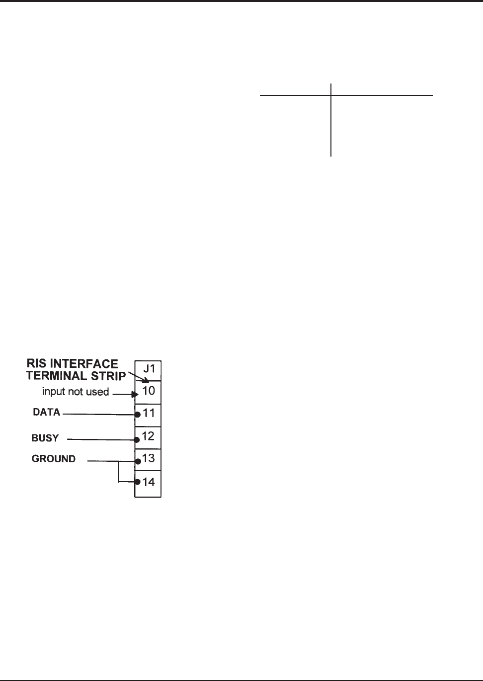
the prepared printer cable as in Figure 3-7.
If the printer cable is screened, ensure that the
screen is grounded at one end only.
When connections have been made and
checked, tighten the cable gland, turn the system
on at SW1 and test the print operation.
Figure 3-7 Non-Bacharach Printer Interface
3.14.5.3 Portable Use of a Non-GMD Printer.
First verify that the printer meets the specification
detailed in Section 3.14.2.
Check the printer manual and identify the wire
color, or pin number, on the printer cable that
correspond to BUSY, DATA and GROUND. If
only the pin numbers are given, open the plug on
the end of the printer cable and write down the wire
color that corresponds.