


REMOTE INTELLIGENT SENSOR - AREA MONITOR
Page 2-4 Instruction 2772-0803
2.6.3 REACTIVE GASES. Many gases are
extremely liable to attenuation and no extension
of input tube should be attempted. These
gases include ISOCYANATES, HYDRAZINES
and ACID GASES such as HF and HCI.
2.6.4 SYSTEM PERFORMANCE WITH
EXTENDED SAMPLE LINES. Bacharach will not
guarantee system performance and accuracy if
extended sample lines are fitted, except where the
company has expressly given written approval.
NOTE: Without such specific approval,
the user must determine that performance
is not adversely affected under the
particular application conditions.
2.7. 0 - 1 VOLT CONVERSION
2.7.1 TOOLS & MATERIALS REQUIRED
• 2.5 mm Hex Key
• Soldering Iron
• Solder
• Wire Cutter (Small)
• Buss Wire (#22 AWG, 1/2" Long)
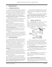
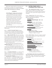
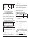
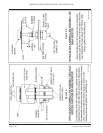
2.7.2 PROCEDURE. Remove main power from
RIS System: then set ON/OFF switch SW1 to OFF.
Follow the removal of the mechanical chassis from
Section 4.11.2.
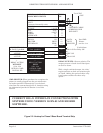
Remove link (0 Ohm resistor) from the 4 - 20
OUTPUT position using wire cutters to cut both
ends of the link. Solder buss wire link into the 0-1
Volt position per Figure 2-1.
Reinstall the mechanical chassis, cables, and
hoses using the first two paragraphs of Section
4.11.5.
Figure 2-1. 0 - 1 Volt Conversion
2.8 SYSTEM CHECK
NOTE: This procedure should be followed
every time a new cassette is installed, to
insure the system is operating correctly.
During the initial system check of this unit,
and at least on a yearly basis there after,
the sample inlet tube should be checked for
proper installation.
2.8.1 TAPE CASSETTE LOADING
WARNING
This involves opening the RIS door, which
automatically initiates the door-open
alarm. Before opening the door to load or
change a cassette, ensure that any external
warning system is disabled or that those
involved are aware of your intended
actions.
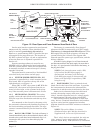
Open the door with the key provided. Leave the
system switch on. Press the TEST Mode switch on
the bottom left inside corner of the door. Open the
tape gate with the lever and remove the old cas-
sette, if installed. The cassette and its mounting
spigots are designed to fit tightly; use a firm and
direct pull to disengage the cassette. See Figure 1-2
for the location of the items referred to.
NOTE: Make sure that the ‘O’ ring
installed in the cassette molding, (and
which seals purge connections), is not left
behind when the cassette is removed.
WARNING
Extended input lines should never be
used when sampling low vapor pres-
sure compounds such as MDI. These
compounds are present in aerosol
form, and sampling efficiency will be
drastically reduced if the sample line
is extended. Instruments intended for
aerosol sampling have a dual input
tube approximately 1" (25 mm) long
protruding from the bottom of the
instrument.
+
-
+
+
-
-
RLA1
RLF
RLA2
SERIAL
PRIN TER
IN TERFAC E
NETW O RK
COM M S
IN TERFAC E
ANALOG
OUTPUT
12VDC
IN PUT
-
+
AOV
AOP
A IN
A O UT
B
S
PI
PO
PRDY
PPRS
OV
RLA2
J1
20
POW ER
ON
SW 1
BATTERY PACK
J4
R16
RLF
RLA1
0-1V
4-20M A
C6
Q1
VR3 SPAN
R13
R11
IC 4
VR2 ZERO
R12
R17
R18
R7
R14
R15
C7
+
IC 2
L1
C5
+
R8 R9
R10
IC 3
D1
C1
R1 R2
IC 1
C2
R3 R4
R5 R6
C3 C4
J5
1
VR1
TR1
1
2
3
4
13
14
15
J3
J2
1
1
GM D 11760
0 - 1 V
4 - 2 0 M A