


REMOTE INTELLIGENT SENSOR - AREA MONITOR
Page 1-2 Instruction 2772-0803
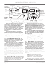
On the main board are mounted several potenti-
ometers and ‘dip’ switches. These should not nor-
mally be touched, particularly dip switch 1.
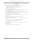
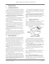
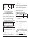
However, a potentiometer (POT) is provided for user
adjustment of the pump flow rate. The location of
the POT is shown in Figure 1-2 and an explanation
of how the flow rate is adjusted is provided in
Section 4.5.
System operating software is stored in two
EPROM’s that are fitted on the board and marked
with the version number. These devices should not
be normally touched or removed except if a factory
upgrade is received.
The main board is protected by a black molded
cover held on by two screws and two pegs.
1.3.4 SYSTEM POWER SWITCH SW1. RIS
operation is controlled by a switch mounted on the
base board. SW1 is located at the top left of the
right hand unit, see Figure 1-2.
When SW1 is ‘OFF’, the system is off. With the
switch ‘ON’, the system will operate from the ex-
ternal 12 volts input, or the systems back-up bat-
tery if the external power is disconnected, or fails.
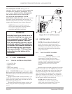
1.3.5 MECHANICAL CHASSIS. This subas-
sembly carries the optic block and its associated
PCB, the tape drive mechanism and take-up drive
clutch.
Also mounted on the chassis is the pump, with
the pneumatic elements and plumbing necessary for
the track switching and purge functions. The tape
cassette is mounted directly on the front face of the
chassis.
1.3.6 BACK-UP BATTERY. The lead acid battery is
located immediately above the mechanical chassis and is
secured to the system base board with metal clips. It is
connected to the system via a short cable plug and
socket (J5).
The battery is automatically ‘float charged’
whenever the RIS is connected to a 12 VDC supply.
The battery is charged with SW1 off or on. If the
RIS supply fails, the back-up battery will keep the
system running for 2-3 hours. The support time
depends upon the system type, specification, and the
battery condition.
If the RIS is being shipped, or will remain unused
and disconnected from the input supply for more than a
few days, it is good practice to disconnect the battery, at
the plug and socket.
NOTE: If the internal system switch, SW1,
is left on and the RIS input supply is
disconnected, the battery will discharge.
If the RIS input supply is disconnected, the
battery will discharge, irregardless of SW1
being on or off.
1.3.7 BASE BOARD. This is a printed circuit
board fixed to the base of the enclosure. It provides
the interconnection between the subassemblies
mounted on it and the main circuit board on the door.
Other circuit elements located on this board
include; the analog output, solid state output
‘relays’, interface terminal strip J1, voltage regula-
tor potentiometer VR1 and system switch SW1.
The current Phase 2 boards have 3 solid state
‘relay’ devices. Terminal identification and number-
ing have varied and the appropriate interface
diagram should be used. Both versions are shown in
Figure 2-3.
NOTE: The earlier (Phase 1) versions
(Produced before April '92) are described in
Supplement A, in the rear of this manual.
The 3 ‘relay’ devices are standard, but only one
‘relay’ output is active and available unless the
optional Alarm Relay PCB (Section 5.5) is installed.
Figure 1-2. Door Open and Cover Removed from Back of Door
B
A
J5
J1
DIP SWITCH 1
DO NOT TOUCH !!
DIP SWITCH 2
OPTION
BOARD
LCD
ADJUST
POT.
EPROMS
DOOR
PROMIXITY
SWITCH
BATTERY PLUG
ON/OFF SWITCH SW1
VOLTAGE REGULATOR VR1
RIBBON
CABLE
INTERFACE
CABLE
PRINTER
SOCKET
BATTERY
FILTER
RED TEST BUTTON
FLOW ADJUST POT.
CABLE GLANDS
TAPE GATE LEVER
TAPE
RESET
BUTTON
LIGHT
LEVEL
ADJUST
MECHNICAL
CHASSIS
PNEUMATIC
HOSES AND
CONNECTOR
DOOR SWITCH
MAGNET
ADJUSTMENT
MAIN BOARD
CASSETTE