


REMOTE INTELLIGENT SENSOR - AREA MONITOR
Page 4-6 Instruction 2772-0803
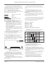
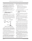
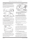
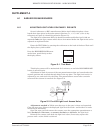
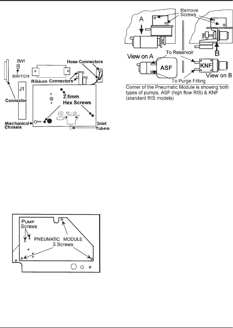
4.11.2 REMOVAL OF THE MECHANICAL
CHASSIS. Remove the cassette, undo the two
ribbon cable connectors and the two hose couplings
in the tubes that connect the chassis to the body of
the instrument. Undo the three (captive) cap head
screws that secure the chassis (see Figure 4-8). A
2.5 mm hex key is required for this. The mechanical
chassis can now be lifted out.
Figure 4-8. Mechanical Chassis
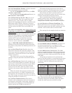
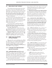
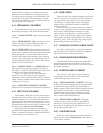
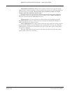
4.11.3 PUMP REMOVAL. Turn the chassis cover
and remove three slot head screws (Figure 4-9) to
allow the pneumatic chassis to be folded out to give
access to the pump. It is not necessary to discon-
nect and remove the module.
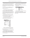
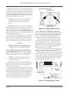
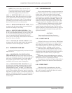
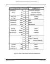
Carefully disconnect tubes to the pump inlet
and outlet. Note original orientation and position,
for trouble free reconnecting. Disconnect input
wiring, and remove screws holding pump which can
now be withdrawn and discarded. Refer to Fig-
ure 4-10 which shows both pump types together
with the orientation of pump connections.
Figure 4-9. Pneumatic Chassis
4.11.4 FITTING THE NEW PUMP. This is a
reversal of the procedure detailed above. Take care
that the correct pump is fitted and that everything
is put back in the original orientation. Make sure
that the pump moving parts are free to rotate
without anything fouling them.
Figure 4-10. Pump Types
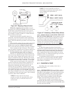
4.11.5 REPLACING THE MECHANICAL
CHASSIS AND SETTING PUMP FLOW. Care-
fully replace the chassis and route the tubes be-
tween chassis and body of the RIS as they were
originally. Check that the tube connections are
oriented correctly. Note, the blue tube (or white in
some cases) should be at the top and the green (or
clear) one should be at the bottom. Reconnect the
ribbon cable connectors, and tighten the three
screws.
The cassette can be replaced and power re-
stored. Switch on SW1 and press the tape reset
button.
Enter the TEST Mode and set the pump flow as
described in Section 4.5.
On completion, return the system to service.
4.12 EXTERIOR CLEANING
An occasional wipe with a damp cloth is ad-
equate in most circumstances. When oily or sticky
deposits build up, a mild detergent solution on the
cloth will normally remove them. Clean with the
door shut and avoid excessive water. It should not
be necessary to clean inside the instrument (except
when cleaning the optics block as described in
Section 4.10.5).
4.13 KEY PARAMETER CHECKS
It is recommended that the TEST Mode checks
are carried out at each cassette change. These are
as described in Section 2.8.
It is good practice to record the reading taken
on the form provided in the back of this manual. If
any value requires adjustment, the reading before
and after should be noted. If a system ‘fault’ occurs
the TEST Mode parameters at the time should be