


REMOTE INTELLIGENT SENSOR - AREA MONITOR
Instruction 2772-0803 Page 2-1
2 INSTALLATION AND
SYSTEM CHECK
The RIS may be installed inside or out. It
should be mounted and connected according to the
instructions provided below, and in an environment
that is within the specified limits detailed in the
Product Specification.
WARNING
Failure to comply with these recommenda-
tions may void the warranty.
2.1 UNPACKING
Carefully check for shipping damage by exami-
nation inside and out. In case of damage, retain
packing and make an appropriate claim against the
carrier.
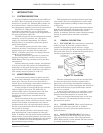
2.2 BATTERY CONNECTION
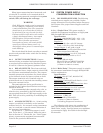
Open the RIS door with the key provided and
reconnect the battery lead at J5 (see Figure 1-2).
NOTE: Do not turn the main system
switch, SW1, on at this stage.
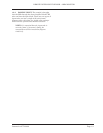
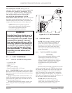
2.3 MECHANICAL INSTALLATION
See Figure 2-6 for enclosure dimensions and
mounting points. When deciding mounting arrange-
ments and position, consider the following require-
ments:
It should be possible to fully open door for
cassette replacement, service and maintenance.
Adequate clearance is required for connection
of external wires and pipes through the glands
provided.
RIS must be located so that the sampling
input tube(s) does not require extending (Section
2.6).
The mounting position should be such that
the installation of other equipment will not subse-
quently interfere with enclosure access.
It should not be possible for strong light,
natural or artificial, to shine directly up the input
tube(s). Servicing will be aided if suitable lighting is
provided.
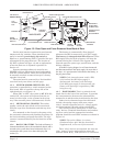
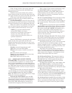
NOTE: Ensure the sample inlet tube(s) are
correctly inserted in the optics block (see
Figures 2-4 & 2-5).
2.4 ELECTRICAL INSTALLATION
2.4.1 CABLE RECOMMENDATION. When
deciding cable size and length, the following criteria
should be used.
The maximum permissible volt drop across
supply cables and termination at an assumed
500 mA = 1 volt. Therefore cable length and size
should be selected so that the maximum resistance
of cable and termination is 2 Ohms.
This requirement is achieved by the cable
recommendations given below. The voltage mea-
sured at J1 terminals 1 and 2 with a system taking a
‘normal’ current of 150-250 mA should be not less
than 11.5 volts.
The following guidance on cable size and maxi-
mum length should be observed:
2.4.1.1 PSU to RIS Input. 18 AWG stranded,
screened, copper wire x 300 ft. maximum, or 16 AWG
stranded screened copper wire x 450 ft. maximum.
2.4.1.2 PSU to Alarm Module. 18 AWG stranded,
screened, copper wire x 600 ft. maximum, or 16 AWG
stranded screened copper wire x 900 ft. maximum.
2.4.1.3 RIS Relay Output to Alarm Module.
Approximately 5,000 ft. maximum of 18 AWG
stranded, screened, copper wire.
2.4.1.4 0 - 1V Analog Output. Dependent upon the
input impedance of the device being driven. Check
with manufacturer. As guidance, with a device
having an input impedance of 10 megohm, a run of
up to 1,000 ft. of 18 AWG stranded, screened, copper
wire should be satisfactory.
2.4.1.5 4 - 20 mA Analog Output. 18 AWG
stranded, screened, copper wire x 500 ft. maximum.
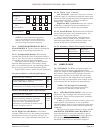
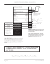
2.4.2 POWER SUPPLY AND INPUT CONNEC-
TIONS. The power supply enclosure can be mounted
adjacent to the RIS, or in some other convenient
location. Advice on power supply selection is pro-
vided in Section 2.5.
Connect the 12 volt DC input from the external
power supply to the J1 interface terminals #1 (0V)
and #2 (+12V). Connect external devices/alarms as
required.