


REMOTE INTELLIGENT SENSOR - AREA MONITOR
Instruction 2772-0803 Page 3-1
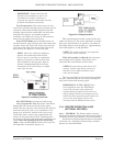
Effective purging requires the enclosure to be
properly sealed. Ensure that the cable glands and
the door are air tight. Unused cable glands can be
tightened onto a short piece of cable.
Purge inlet and exhaust ports can be piped to a
remote location, where this is necessary.
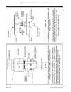
3.1.2 TWIN TRACK TAPE SAMPLING. At
start-up the incoming sample is passed through the
lower tape half (track 1). When that sampling period
is complete, the microprocessor decides if a stain has
formed on the tape. If not, the next sample is again
passed through the same spot on track 1. Conversely
if a stain was formed, the second sample is switched
to pass through the upper half (track 2). The same
sequence occurs at the end of that sample period and
track 2 is reused if no stain is detected.
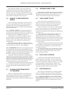
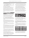
At this point the tape is stepped on and the next
sample passed through the next track 1 spot. Figure
3-2 shows the sequence where no stain develops and
the maximum of four sample periods occurs before
the tape is stepped.
Figure 3-2. No Stain, Both Tracks Used Twice
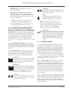
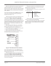
Figure 3-3 shows that only two sample periods
per tape step occur if significant stains develop on
the tape.
Figure 3-3. Stain On Tape, Both Tracks Used Once
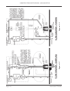
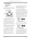
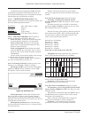
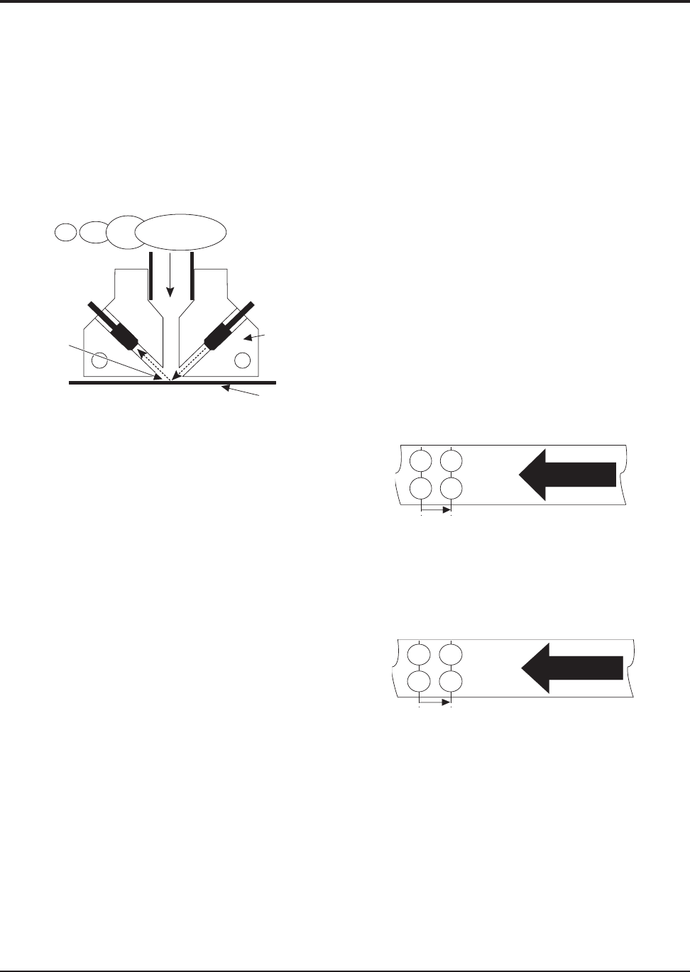
3.1.3 TAPE REFERENCE MEASUREMENT. At
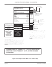
the start of each sample period, the tape spot being
used is scanned by the light pulse (generated by the
optics system), see Figure 3-1. The value of the
reflected light is measured and stored as the refer-
ence against which the light value, during and at the
end of the sample period, is assessed..
3 SYSTEM OPERATION
AND FEATURES
3.1 COMPLETE SAMPLING
SEQUENCE
The sequence starts with system and cassette being
purged before gas sampling starts. In addition, a
reference light level reading is taken from the fresh
tape spot under the optics block.
Figure 3-1. Sampling Sequence
During the sampling period the tape spot is
scanned every two seconds. This frequent scanning
detects the change in the reflected light value that
occurs if a stain develops.
If no stain, or a low density stain, is detected,
sampling continues for a fixed four minutes. At the
end of this time calculated concentration for that
cycle is displayed and the next cycle starts.
The development of a significant stain shortens
the sampling cycle and the concentration value is
displayed immediately, as described in more detail
below.
When a concentration above alarm set point is
detected, the gas alarm relay/s opens to initiate
external alarm systems and warning devices. This
is in addition to the visual warning display.
3.1.1 AUTOMATIC PURGE CYCLE. A purge
sequence occurs after every tape step. The pump
runs at a higher Flow Rate for 10 seconds; air
inside the tape cassette, and the enclosure, is
exchanged for filtered air. The incoming air is
filtered as it passes through a ‘scrubber’ filter in
the cassette. This is shown in the diagram in
Figure 2-8.
Purging prevents the build up of gas in the
system, and in the cassette where it could pre-
expose the tape. The ‘scrubber’ filter is automati-
cally renewed at each cassette change.
TAPE
3/4 7/8
1/2 5/6
STEP
4 SAMPLE PERIODS OF 4 MINUTES EACH
= 16 MINUTES PER TAPE STEP
TRACK 2
TRACK 1
TAPE
2 4
1 3
STEP
2 SAMPLE PERIODS PER STEP. EACH SAMPLE
PERIOD IS A MAX OF 4 MINUTES, OR LESS IF
THE STAIN IS SIGNIFICANT = 8 MINUTES PER
TAPE STEP
TRACK 2
TRACK 1
PHOTO
DIODE
LIGHT
REFLECTED
OFF TAPE
SURFACE
INCOMING
SAMPLE
LIGHT
EMITTING
DIODE
OPTIC
BLOC
K
TAPE