


REMOTE INTELLIGENT SENSOR - AREA MONITOR
Instruction 2772-0803 Page 1-1
1 INTRODUCTION
1.1 SYSTEM DESCRIPTION
A range of Remote Intelligent Sensors (RIS) are
available. Each is designed to measure low concen-
trations of a specific gas. Multiple RIS systems can
be connected into a control network to provide an
area monitoring capability with central supervision.
The RIS is a single point, microprocessor
controlled, instrument for use in a fixed location.
Two RIS versions were produced (see Supplement A
for units built before April '92).
The RIS is housed in an environmentally sealed
enclosure and is line-powered, via a DC power
supply, for continuous monitoring. An internal
backup battery is provided as protection against
power interruptions.
The standard system provides clear visual
indication of status, concentration level, 4-20 ma
analog output, gas, and fault alarm conditions.
TWA’s, 15 minute and 8 hour, are displayed at the
touch of a keyboard button.
Reliable and effective operation is assured by
on-line self-diagnostic routines. An easy-to-use
TEST Mode allows key parameters to be checked
and adjusted.
Optional features provide storage, and printout,
of up to one week’s data points, two independently
selectable (via keypad) alarm relays with a separate
fault indication relay and a hardware selectable 0-1
VDC analog output (Sections 2.4.5 & 2.7).
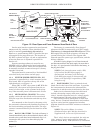
1.2 BASIC PRINCIPLES
A measured sample volume is drawn into the
RIS and passed through a chemically impregnated
paper tape. The tape reacts to the presence of a
specific gas by developing a stain whose intensity is
proportional to the sample concentration.
A beam of light is bounced off the tape and the
reflected light is measured. The difference in
reflected light values, developed before and after
the stain, is used to calculate stain intensity,
enabling the sampled gas concentration to be
determined.
The measurement of low gas concentration
levels takes place during a fixed four minute sample
period. If the sample concentration rises above a
predetermined value, the operating mode changes
and the system measures the time taken for a given
stain value to develope.
This technique provides a wide dynamic range,
good resolution and a rapid response to rising gas
levels. In addition, the tape never becomes saturated
which ensures accurate measurement, and toxic gases
are prevented from breaking through the tape into the
system. A double track, tape management system
gives maximum tape economy.
This combination of operating features gives long
tape cassette life at low sampling levels, and a rapid
response with excellent tracking of short term peaks
as levels rise.
The detection of a gas concentration that is higher
than the user-adjustable alarm set point, results in a
highly visible warning on the RIS's large custom
display. In addition, local and remote external warning
devices or systems can be activated via interface
signals.
1.3 GENERAL DESCRIPTION
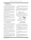
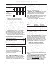
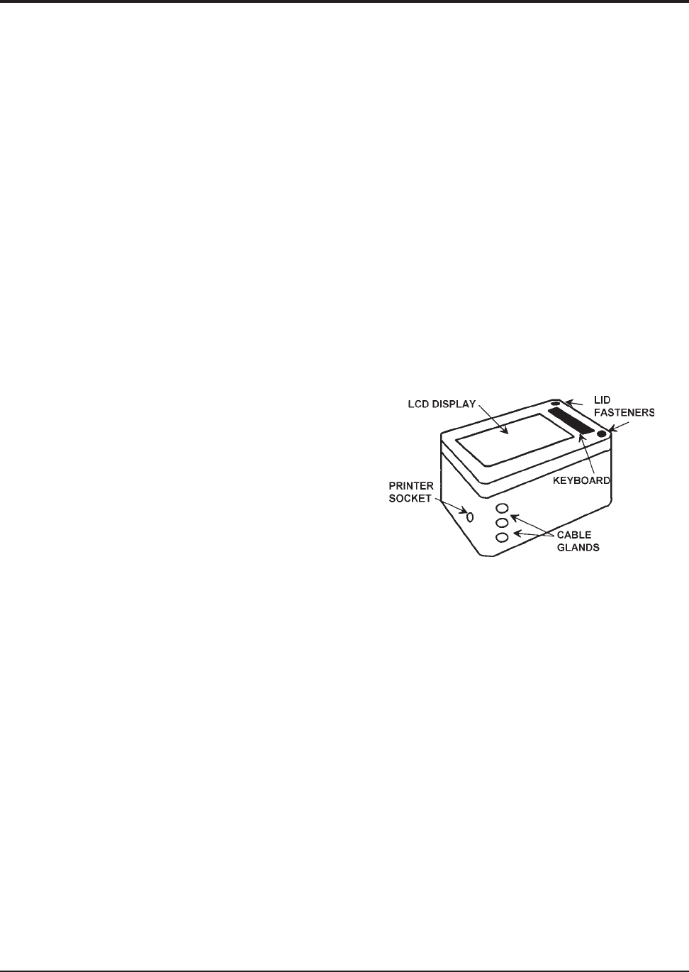
1.3.1 ENCLOSURE. The instrument is contained
within a tough, IP-55 rated, enclosure that is
suitable for installation inside and out. A large
liquid crystal display (LCD) is mounted in the front
face of the door next to a membrane keyboard that is
used for programming certain functions.
Figure 1-1. Enclosure
The door is hinged on one side and secured shut
by two screw fasteners, which are opened with a
special key to discourage unauthorized tampering.
The door hinges are easily disengaged and removal of
the door from the base is quick and simple, should
this ever be required.
A door-open fault display icon, and relay output
provide warnings and help ensure that RIS is only
operated when the enclosure is secured shut.
There are threaded mounting holes in the base
of the enclosure. The mounting brackets are sup-
plied with the system.
1.3.2 CABLE GLANDS. Three sealed glands are
provided for cable entry and exit. A socket is
provided at one end to allow the connection of an
optional printer.
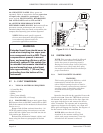
1.3.3 MAIN SYSTEM BOARD. The board is
mounted on the rear face of the door and is acces-
sible when the door is open. The red push-button
TEST Mode switch is in the bottom left-hand corner,
as viewed with the door open.