


REMOTE INTELLIGENT SENSOR - AREA MONITOR
Page 2-6 Instruction 2772-0803
Alarm Level 1 is displayed first and is identified by
the number 1 which is shown in addition to the
numerical set point value. Similarly, the Alarm level
2 set point which follows, is identified by a 2.
IMPORTANT: Be aware that if the RIS is
switched off at SW1, the alarm set point(s)
will be return to their default at system
switch on. It will therefore be necessary to
reestablish set points if they differ from the
default values.
2.8.2.5 Gas Curve. The gas curve for the system is
displayed as a number. Systems are fitted with an
alpha numeric display and the active gas curve
shown directly (e.g., MDI or TDI etc.). Most systems
have only one gas curve programmed in the soft-
ware and that curve is permanently active.
2.8.2.6 Multi Gas Curve Systems. In special
‘multicurve’ systems, a curve can be selected by:
1. Pressing TEST switch to enter the TEST Mode.
2. Wait until the display scrolls to the gas curve.
3. Press HOLD key to freeze the display.
4. Press DIGIT key to select the required curve.
5. Exit the test mode.
NOTE: The ‘default’ curve is MDI and is
automatically selected at system power up.
2.8.2.7 Light Levels Track 1 & 2. The next
display in sequence, is track 1 light level value.
This is a numerical value between, approximately,
200 and 254. Also displayed is a separate 1 (for
track one). This is followed by the next display with
a similar reading and a 2 (for track two).
The ‘correct’ value for both light levels is 220.
However, variations occur normally because of
small changes in the reflective property of the tape
along its length. These variations do not normally
exceed ±2 or 3. If the light level reading is 220 ±2 or
3, do not adjust. If it is approaching 200, or more
than 235 it should it be reset to 220.
NOTE: The light level may vary slightly
tape to tape. It is essential that checking
and adjustment is only made with a tape
in the gate and the gate closed. See Section
4.4 for detailed instructions on adjustment.
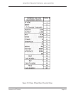
2.8.2.8 Flow Rate. While the light level test cycles
are active, the pump is running and ‘sample Flow
Rate’ can be checked. This is done by HOLD-ing the
display at 1. (and afterwards at 2.), and measuring
Flow Rate with a suitable flow meter connected in
series with the sample inlet tube.
Be aware that each system has its particular
Flow Rate as shown in Table #1. After track 1 flow
has been read, press the HOLD/RELEASE key to
‘release’ the display. Allow it to step to track 2 and
press the key again to ‘hold’ that reading.
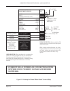
Flow to both tracks is supplied by one pump and
switched to the active channel by solenoid valves.
The flow measured at each track should therefore
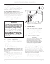
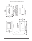
be similar. Adjustment to the pump flow is made
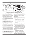
with the potentiometer located on the main board as
shown in Figure 1-2 and is described in Section 4.5.
2.8.2.9 Date & Time. If the Optional Printer card
is installed, the data displayed in the Test sequence
automatically includes the date and time. The date
and time are reset to zero, with any stored data
point information, when the system is switched off
at SW1. It is necessary to set the date & time when
the system is installed, and if it is switched off
subsequently.
'HOLD' Setting Date & Time. To set the date
and time, ‘hold’ the display and use the digit and
decade keys to select the required values. The
decade that flashes after the display is ‘held’ is
adjusted first in each case.
If the number required is stepped past, keep
going until the desired number comes round again.
Note that the date & time is not lost if the input
supply fails, providing the back-up battery is not
discharged and SW1 remains on.
2.8.2.10 Interruption of TEST Mode Cycle. If
5 minutes have elapsed since entering the Test
Mode, the display will revert to “normal”. To
complete the adjustments, press TEST Mode switch
again to reenter the mode and carry on.
2.8.2.11 Completion of Checks. Exit the TEST
MODE by pressing the red TEST BUTTON again on
the rear of the door.
NOTE: It is occasionally possible to
initiate a display that contains both
‘normal’ and ‘test’ data simultaneously. If
this occurs when exiting the TEST Mode,
press red TEST MODE button to reenter
the mode and then again to exit it cleanly.
When installing a new tape, press the red TAPE
RESET button on the left of the tape gate to reset
the system and the tape counter.
Close the door and tighten the securing screw
fasteners. The display should now show: SYSTEM
OK and a zero NUMERICAL ppm/ppb value
(assuming monitored atmosphere is zero) alternat-
ing with 99% which indicates the cassette life
available. There should be no fault icons shown.