


REMOTE INTELLIGENT SENSOR - AREA MONITOR
Page 3-6 Instruction 2772-0803
In addition to that supplied by GMD, printers
meeting the specification detailed below may be
used. Those intending to use an alternative printer
should check the specification carefully.
3.14.2 PRINTER SPECIFICATION. The
printer must be capable of receiving serial data and
meet the following requirements:
Baud Rate: 600, 1200, 2400, or 9600
bits/sec.
Stop Bits: 2 bits
Word length: 8 bits Parity:
Even Signal Level: TTL Logic Type: Positive
3.14.3 PRINTOUT MODES. Three modes of
printer operation are provided. They are:
Print ‘On Line’. In this mode each data point
is automatically printed as it is generated.
Print at Intervals. The data is stored and
printed out at predetermined intervals. The
interval is user selected.
Print on Command. Data points are stored
until the PRINT key is pressed. Up to 7 day’s
worth of data can be stored for print out when
commanded.
In each of the above printer modes, the storage
is cleared when the data is printed out.
If necessary, printer storage can be cleared at
any time as described in Section 4.9.
3.14.3.1 Printing ‘On Line’ (printing every data
point as it is calculated). Select by setting:
Switch # 1 of SW1 switch bank on the Printer
Module to ‘OFF’ and set switches 2 to 8 to ‘ON’.
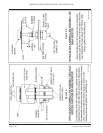
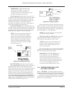
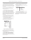
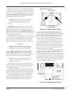
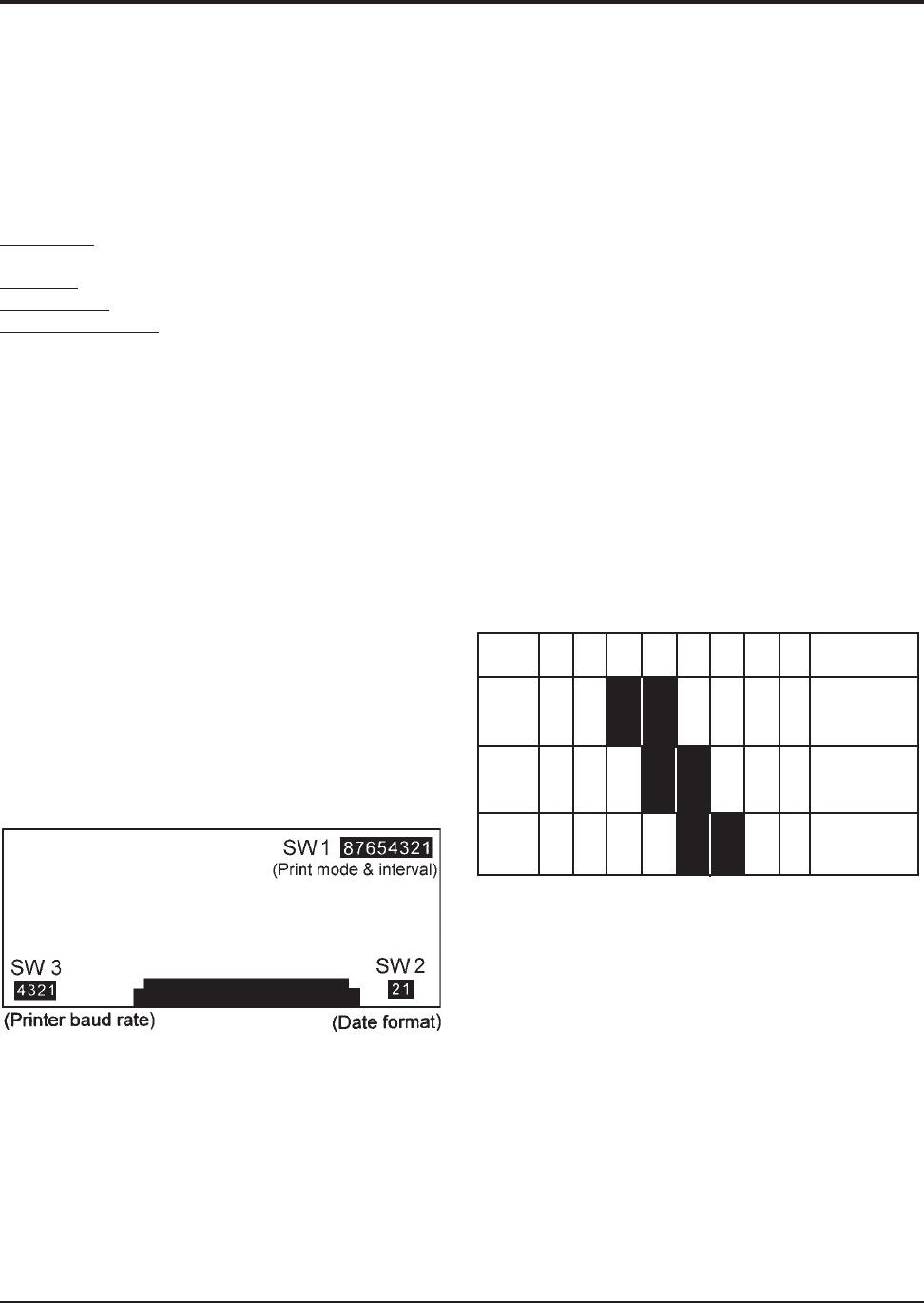
See Figure 3-6 for switch location.
Figure 3-6. Switches 2 & 3
Initial printout in this mode includes: date,
time, tape left %, battery volts, battery charge
(total system current in mA), alarm level and the
monitored gas concentration. Also shown are gas or
fault alarms, if these occur.
Subsequent printouts show only the time
and concentration, unless there is a system fault or
an alarm present.
Where it occurs, gas alarm, or type of fault
detected, is printed out next to the time and concen-
tration.
3.14.3.2 Print at Intervals. Select by setting:
Switch # 1 of SW1 switch bank on the
Printer Module to ‘ON’. See Figure 3-6 for switch
location.
Printing intervals are available in 30 minute
increments up to 24 hours. Intervals are set with
SW1 switches # 3 to # 8, as follows.
Switch # 3 to # 8 each enable a discrete period of
time when turned ‘OFF’. Each enabled switch adds
its time value to achieve the total required. The
value of each switch when ‘OFF’ is:
Switch # 8 = 30 minutes
Switch # 7 = 1 hour
Switch # 6 = 2 hours
Switch # 5 = 4 hours
Switch # 4 = 8 hours
Switch # 3 = 16 hours
Switch # 2 is not used and is left ‘ON
Examples: For print intervals of 6, 12 and 24
hours, SW1 switches would be set as follows:
SW1 #8 #7 #6 #5 #4 #3 #1 TOTAL
on on off off on on on
Time 0 0 2 4 0 0 -- = 6 hour
on on on off off on on
Time 0 0 0 4 8 0 -- = 12 hour
on on on on off off on
Time 0 0 0 0 816 -- = 24 hour
Any combination of the switches can be used to
select an interval up to 24 hours.
Printout: A full printout of all measured
parameters occurs at each interval.
3.14.3.3 Print on Command. Select by setting:
All switches ( # 1 to # 8) of SW1 switch bank
on the Printer Module to ‘ON’. See Figure 3-6 for
switch location.
The printout is initiated when the PRINT key on
the RIS front panel is pressed. The entire stored
data points are printed out.
Data is not lost if the PRINT key is inadver-
tently pressed without a printer connected.
Printout: A full printout of all measured
parameters occurs at each printing occurrence.