


REMOTE INTELLIGENT SENSOR - AREA MONITOR
Page 2-8 Instruction 2772-0803
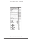
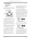
TERMINAL USE AND TERMI-
SILKSCREEN IDENTS NAL
12 VDC – 1
INPUT + 2
(Connected internally to #1) 3
ANALOG – A 0V 4
OUTPUT + A OP 5
NET- A IN 6
WORK A OUT 7
COMMS B 8
INTERFACE S 9
PI 10
SERIAL PO 11 DATA Non GMD
PRINTER PRDY 12 BUSY Printer
INTERFACE PPRS 13 GROUND see Sec. 3.14
0V 14
COMBINED GAS RLA1 + 15 + Fault/Alarm
& FAULT ALARM GAS ALARM 1 – 16 RLA1 O/P or Relay O/P
NOT RLF +17+
ACTIVE FAULT ALARM – 18 RLF O/P
NOT RLA2 +19+
ACTIVE GAS ALARM – 20 RLA2 O/P
s s
RELAY ACTION RELAY ACTION
WITHOUT WITH
2701-1761 2701-1761
OPTION CARD OPTION CARD
INSTALLED INSTALLED
CURRENT RIS J1 INTERFACE CONNECTIONS WITH
SYSTEMS USING VERSION 30-XX-03 AND HIGHER
SOFTWARE.
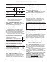
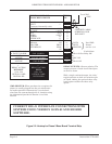
Figure 2-2. Hookup for Phase 2 Base Board Terminal Strip
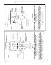
RELAY OUTPUTS: Observe polarity. The
outputs present a closed circuit that opens
on fault or alarm.
With a single combined output, the ‘relay’
toggles position on fault and remains open
on alarm. Adding the optional three-relay
board option enables the three-relay
option.
GMD PRINTER: When purchased as an option, the
printer is usually plugged into the pre-wired exter-
nal socket provided. Alternatively it can be hard-
wired into the system through the J1 interface using
the information provided in Section 3.14 of this
manual.
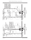
CONNECT CABLE
SCREEN(S) ONE
END ONLY
To 12 VDC
+PSU