


REMOTE INTELLIGENT SENSOR - AREA MONITOR
Instruction 2772-0803 Page 4-3
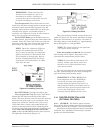
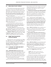
4.8 MEASURING PUMP CURRENT
To establish the pump run current, first check
the system current in the TEST Mode. Then the
total current is measured as detailed below and the
TEST Mode current deducted from total current to
give pump current. If the printer option is fitted,
the total current is shown on the printout header. If
it is not, total current can be measured with a
suitable multimeter in series with the RIS 12 VDC
input at J1 terminal #2.
When the meter has been connected, switch the
RIS on and take a reading during the normal
sampling period. This starts immediately after the
purge cycle. Do not measure the current during the
purge cycle because the pump is running at a
higher than normal rate.
It is not necessary to check the pump run
current frequently but an excessive current is a
good indication that a pump requires attention, or
replacing. The following ‘normal’ range of pump
current is provided for guidance.
Low Flow Pump, RIS systems with a flow
rate of 250 mL/min. or less: ‘typical’ current range =
90 to 120 mA. A pump current of 200 mA or more
indicates a faulty pump that requires replacement.
High Flow Pump, RIS systems with a flow rate
of 700 mL/min. or more: ‘typical’ current range = 250
to 300 mA. A pump current of 400 mA or more
indicates a faulty pump that requires replacement.
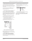
4.9 RESETTING THE PRINTER
OPTION STORAGE
The stored data can be cleared any time. Enter
the TEST Mode, press the HOLD/RELEASE key at
any point in the cycle, and then press the PRINT
key. Exit the TEST Mode to return to normal
operation. Storage resetting can be verified by
initiating a printout. The header will show ‘printout
CANCELED’ in acknowledgment.
4.10 CLEANING THE SAMPLING INPUT
AND OPTICS BLOCK
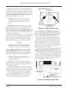
4.10.1 INTRODUCTION. The RIS draws the
atmosphere to be monitored through the optics
block. This assembly conveys the sample to the tape
and houses the LED’s (light emitting diodes), and
photodiodes. These devices, respectively, initiate
and receive the beam of light that is bounced off the
tape and used to determine the sample concentra-
tion by measuring the stain density.
If the sample drawn through the optics block
contains dust, other airborne particles or aerosols,
these substances will, in time, tend to coat the optic
elements mentioned above. In addition, they may
accumulate in the input tube and the air path
through the optics block.
The effect of this process is to gradually degrade
the performance of the optics block. This deteriora-
tion can progress to the point where the light level
adjustment is no longer able to compensate. When
this occurs, remedial action is necessary. The
following information provides guidance on light
level adjustment and cleaning procedures.
4.10.2 LIGHT LEVEL ADJUSTMENT. The
acceptable light level range, (checked in the TEST
Mode), is between 200 and 254 and applies to both
tracks. Recommended practice is to check the levels
at each cassette change and adjust to 220 on the
tape being used. The 220 value allows for small
naturally occurring changes in level, without the
extremes of 200 or 254 being reached. The ad-
justment procedure is provided in Section 4.4.
4.10.3 WHEN TO CLEAN. Unless conditions are
adverse, it is unusual for the air paths to need
cleaning more frequently than every 9 to 12 months.
Be guided by experience and adjust cleaning
frequency accordingly.
An exception to the norm is where there are
significant sticky aerosols present in the monitored
atmospheres. This situation can occur when MDI is
sampled. In such cases careful regular cleaning of
the input tube, and the air path through the block,
may reduce the need for more extensive cleaning.
An indicator that cleaning is required is an
inability to restore the light levels to the 220 value
by means of the adjustment provided.
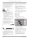
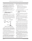
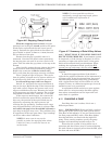
4.10.4 HOW TO CLEAN. To clean the input tube,
unscrew the external clamping nut and the input
assembly parts can be withdrawn. The actual
sample tube can be easily gripped and removed if a
short piece of a larger diameter silicone rubber
tubing is put over it.
When it has been removed, clean the input tube
with a cotton tipped swab (or similar) and, if re-
quired, use a residue free solvent spray.
NOTE: RIS’s with two input tubes (e.g..
MDI systems) have different parts but the
method of disassembly is similar.
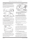
To clean the air passage in the block, put a piece
of tape into the gate (tape from an old cassette can
be used) and close it. Blow into the sampling port
side of the block (after the input tube has been
removed) to shift dust and loose debris. Then, open
the gate and move a clean piece of tape into position.