


Service Reference Manual UNIT COMPONENTS
5-25
SRM-HW/HWC 2/99
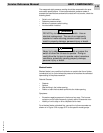
What Is Needed for the Tests
• A good general-purpose incline manometer with a range of 0 - 3"
W.C. (Dwyer 1227 or equivalent).
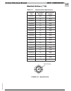
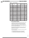
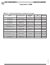
• Use the parts list to verify that the proper pressure switch is installed
in the unit. Look for the Armstrong part number stamped on the
metal housing. A label on the housing shows the manufacturer’s
model number.
• Find the Switch Open value for the pressure switch in Table 5-4 on
page 22.
• Assorted lengths of plastic tubing and tees to make the connections
to the manometer including the following: 1/8" I.D. high temperature
silicone tubing, 1/4" I.D. vinyl tubing, 1/8" tee and 1/4" tee.
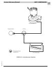
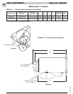
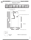
Note: For each procedure, the schematic shows the original factory
tubing with solid black lines. The tees to be installed for pressure
sampling are shown within the dashed circles.
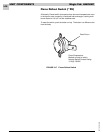
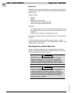
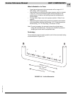
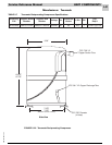
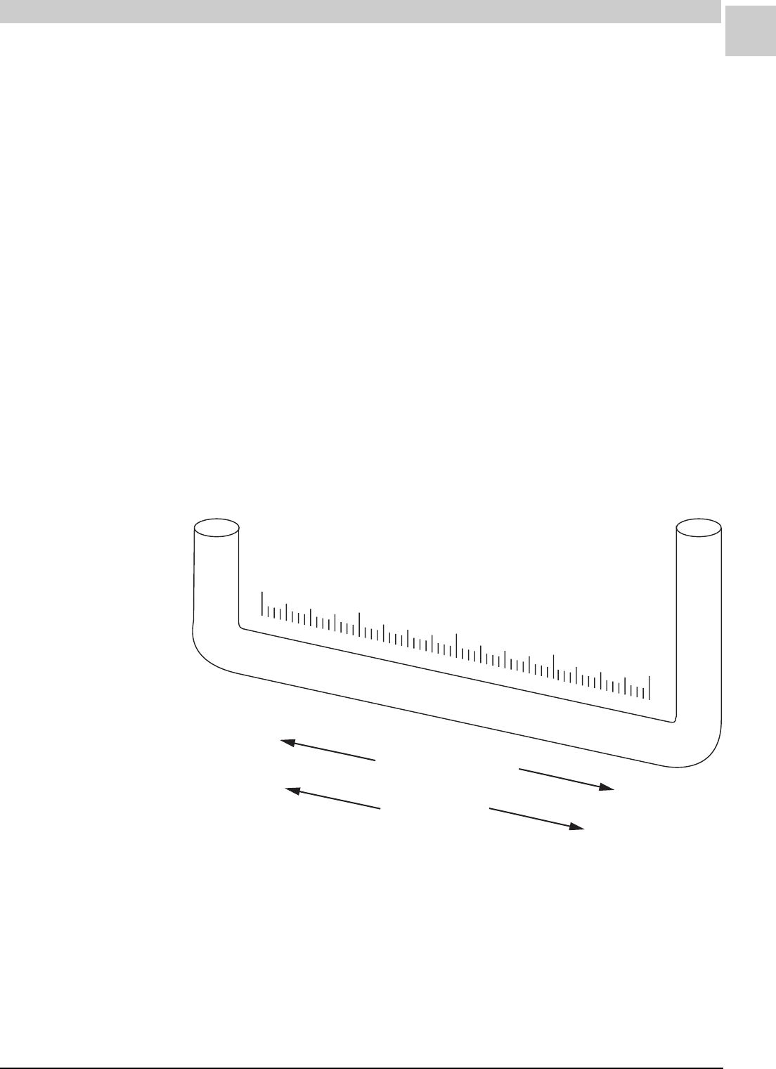
Terminology
Terms related to pressure switch operation and incline manometer testing
are shown below in Figure 5-19.
FIGURE 5-19 Incline Manometer
0
-1"
1"
2"
3"
BA
“Negative” pressure
“Positive” pressure
“Pressure Rise”
“Pressure Fall”