


SPECIFICATIONS Magic-Pak: HW/HWC
2-12
SRM-HW/HWC 2/99
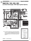
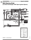
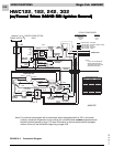
Detailed Sequence - HW (w/UTEC 1097 Board)
Refer to Figure 2-2
POWER
Line Voltage
With the unit at rest (no call from the thermostat), line
voltage will be present:
L1 Power
1. Through the L1 black lead to the L1 terminal on the
ignition control
2. At the transformer terminal marked 208-240V
L2 Power
1. Through the L2 black lead to the induced draft
blower
2. Transformer common terminal
3. At the circulating air blower capacitor terminal
Low Voltage (24 VAC)
With the unit at rest (no call from the thermostat), 24
volts A/C will be present:
1. At the transformer 24V terminal
2. At the 24VAC hot terminal on the ignition control
3. At pin 5 of the 5-pin thermostat harness (red wire
pin)
4. At pin 6 of the 6-pin ignition wire harness
5. Through the auto reset limit switch and the
manual reset rollout switch to pin 1 of the 6-pin
ignition wire harness
Note: While the unit is at rest, the green LED shows
consistent slow flash. This indicates normal
operation - system at rest (standby mode).
CALL FOR HEAT
Line Voltage
The ignition control receives a signal from the R-W
circuit indicating a call for heat.
1. The combustion blower relay energizes, sending
L1 power to CMB BLWR terminal on the ignition
control. This causes the combustion blower to
start.
2. As the 24-volt signal is sent to pin 4 of the 6-pin
ignition wire harness by the ignition control, a 30-
second circulating air blower “on” delay starts.
After the delay, the ignition control energizes the
heat speed blower relay. This sends L1 power to
the ACB HEAT terminal on the ignition control.
3. L1 power is then sent to the circulating air blower
terminal block where it is connected to the blower
motor, starting the circulating air blower.
4. The combustion blower and the circulating air
blower continue to run until the R-W circuit is
interrupted. After a 5-second post-purge delay, the
CMB BLWR terminal on the ignition control de-
energizes. This interrupts L1 power to the combus-
tion blower. After a 120-second circulating air
blower “off” delay, the ACB HEAT terminal de-
energizes. This interrupts L1 to the circulating air
blower. As L1 power is interrupted, the blowers
shut off.
Low Voltage
1. A call for heat closes the R-W circuit, sending a 24-
volt signal to the low voltage white wire in the unit.
2. The 24-volt signal is received at pin 3 of the 5-pin
thermostat harness on the ignition control.
3. The 24-volt signal causes the combustion blower
relay to close, causing the combustion blower to
run. At this time, a 24-volt signal is also sent out
through pin 2 of the 6-pin ignition wire harness.
4. The 24-volt signal from pin 2 of the 6-pin ignition
wire harness energizes one side of the Normally
Open pressure switch. As the induced draft
blower reaches full speed, the pressure switch
closes and a 24-volt signal is sent to pin 5 of the 6-
pin ignition wire harness.
5. When the 24-volt signal is received at pin 5 of the 6-
pin ignition wire harness, the ignition control starts
a 30-second pre-purge delay.
6. After the 30-second pre-purge, the ignition control
initiates a trial for ignition. The spark ignition
cable terminal and pin 4 of the 6-pin ignition wire
harness energize simultaneously.
7. When the 24-volt signal is present at pin 4 of the 6-
pin ignition wire harness, the ignition control starts
a 30-second circulating air blower “on” delay.
8. The 24-volt signal from pin 4 of the 6-pin ignition
wire harness is received at the gas valve, causing
it to open and the burners to ignite.
9. After 30-second “on” delay, the circulating air
blower relay energizes the heat terminal and the
circulating air blower is energized.
10. The unit will continue to operate normally until the
R-W circuit is interrupted.
11. When the heat call is satisfied, the thermostat will
interrupt the R-W circuit. This causes the 24-volt
signal to the white wire in the unit to be de-ener-
gized.