


Service Reference Manual SEQUENCE OF OPERATIONS
2-17
SRM-HW/HWC 2/99
Detailed Sequence follows
CALL FOR COOLING
1. A call for cooling closes the circuit from R to Y and
G.
2. A 24-volt signal is sent to blower control board
terminal G and to the compressor contactor. The
contactor closes, sending line voltage to the com-
pressor and the outdoor condenser fan.
3. With a 24-volt signal at terminal G on the blower
control board, the circulating air blower starts in
cooling speed approximately 15 seconds later (or
immediately - see note below).
4. When the cooling call is completed, G and Y de-
energize. The contactor opens immediately, stop-
ping the compressor and the outdoor cooling fan.
When G de-energizes, the timer to turn off the
circulating air blower starts. The circulating air
blower turns off after 90 seconds (see note below).
FAN ON
1. When the thermostat switch is moved to the “FAN
ON” position, the circuit between R and G closes.
2. The 24-volt signal from G goes to the blower control
board which starts the timer.
3. Fifteen seconds after terminal G on the blower
control board energizes (or immediately after - see
note below), the circulating air blower starts.
4. When terminal G on the blower control board de-
energizes, the timer to turn off the circulating air
blower starts. The circulating air blower turns off
after 90 seconds (see note below).
Note: Heatcraft blower control boards have a G “on”
delay of 15 seconds and an “off” delay of 90
seconds. Tridelta blower control boards have no
“on” time delay and a 60 -130 second “off” delay.
CALL FOR HEAT
1. A call for heat closes the circuit between wires R
(red) and W (white) on the unit’s thermostat connec-
tions.
2. A low voltage (24 volts) signal is sent to the ignition
control, closing a relay which sends line voltage to
the induced draft blower. At the same time, a 24-
volt signal is also sent to the blower control board.
This causes the blower control board to begin the
countdown to closing the relay that starts the
circulating air blower.
3. After the induced draft blower creates enough
negative pressure, the pressure switch closes.
4. When the pressure switch closes, the 24-volt signal
is sent to the ignition control. This starts a 30-
second pre-purge countdown, after which a trial for
ignition is made.
5. At the same time that the trial for ignition is made,
the gas valve energizes and gas flows to the
burners.
6. With the burners in operation, the trial for ignition
continues for seven seconds. At the end of this
time, the ignition control stops sparking.
7. Approximately 30 seconds after the burners ignite,
the timer on the blower control board closes a relay,
sending line voltage to and starting the circulating
air blower.
8. The unit continues to operate as long as there is a
24-volt signal between R and W. When the call for
heat is satisfied, the 24-volt signal between R and W
discontinues. When W de-energizes, the power to
the induced draft blower and the gas valve is
interrupted. The 24-volt signal to the blower control
board is also interrupted, causing the module to
start the countdown to blower “off” (approximately
90 seconds).
9. If at any time during a call for heat the limit switch
opens, the 24-volt signal to the white wire going to
terminal P.SW on the ignition control is interrupted.
This de-energizes the gas valve immediately. The
circulating air blower and the induced draft blower
continue to run. When the unit cools down enough
for the limit switch to close, the 24-volt signal is
again sent to the P.SW terminal on the ignition
control. With terminal P.SW energized, the ignition
control again makes a trial for ignition and relights
the burners.
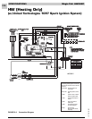
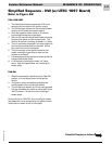
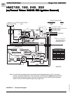
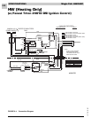
Simplified Sequence - HWC122,182, 242, 302
(w/Fenwal Triton 2461D DSI Ignition Control)
Refer to Figure 2-3